Drag Chain & Wiring
This section covers mounting the drag chain and wiring.
Attach Drag Chain Rail
Core Components Kit
SKU
Name
Qty
25286-38
Button Head Cap Screw M5 x 12
4
1000mm Drag Chain Kit
SKU
Name
Qty
26049-09
Extrusion T-Slot 20x20 x 1000mm Tapped
1
25286-46
Button Head Cap Screw M5 x 14
2
30681-01
Drag Chain Support Arm
2
In this step we will be installing the drag chain support arms through the Y plates and into the remaining threaded holes on the X axis extrusion.


Starting on the left side, position the drag chain support arm with the extrusion mount angling down (as shown). Secure the drag chain support arm through the Y plate and into the X axis Makerslide rail with two M5x12mm button head cap screws. Tighten with a 3mm hex key. Repeat this process for the other side. If you haven't already, tighten the screws that mount the side plate to the Makerslide as well.
Place an M5x14 button head screw through the hole in the plastic support arm and thread it onto the end of the 1000mm extrusion. Repeat this process for the other side and tighten the screws with a 3mm hex key.

If broken during assembly, you can find an additional Drag Chain Support Arm in the Spare Parts Kit.
Install Drag Chain and Wiring
1000mm Drag Chain Kit
SKU
Name
Qty
Drag chain
2
30554-06
M5x10mm Flat Head Screw
2
M5 Post-assembly Tee Nut
2
M5x12mm Flat Head Screw
2
30265-10
M5 Nyon Lock Nut
2
Prepare the drag chain lengths by popping open the hinges using a small flat head screw driver.


Using a flat head screw driver, carefully remove the last link of the drag chain on the side where the the link is flipped upside-down from the open links (see below image).
Insert 2 M5 post-assembly tee nuts into the top side near the center of the drag chain extrusion we just mounted to the Y plates. Place the Drag chain link that was removed over the tee nuts oriented such that the circular portion of the end link is facing the right-hand side of the machine. Loosely secure the end link to the post-assembly tee nuts using 2 M5x10mm flat head screws and a 3mm hex key.


Attach Z-Probe
If you ordered your machine with a Z-Probe, you can now fasten the Z-Probe barrel connector port and its wire to the x-carriage, otherwise, you can skip this step.
First, open your z-probe kit. Set aside the puck and alligator clip wiring harness for the moment; you'll use these to calibrate your machine after it's set up.
Locate the long wire with the barrel connector port as well as the slim hex nut and lock washer that accompany it.

Insert the barrel connector port into the corresponding hole on the top right side of the Z probe relocation bracket on the X-Carriage. Use a 10mm wrench to secure the port in place, placing first the lock washer and then the hex nut over the port. Be careful to not over-tighten the nut, as the connector is fragile.

If the wire is damaged during installation, you can find another Z-Probe Wiring harness in the Spare Parts Kit.
Attach the drag chain end to the drag chain bracket oriented such that the drag chain is going towards the right side of the machine. Place a M5x12mm flat head screw through the end of the drag chain and through the drag chain bracket that's attached to the X carriage. Secure the M5x12mm flat head screws with M5 nylon lock nuts and tighten using a 3mm hex key and 8mm wrench.


Connect the Motor and Homing Switch Cables
SKU
Name
Qty
30679-09
X Axis Motor Cable
1
30679-12
Z Axis Motor Cable
1
30682-07
X Axis Homing Switch Cable
1
30682-09
Z Axis Homing Switch Cable
1
30680-01
Zip Tie Mount
5
30679-11
Y2 Axis Motor Cable
1
30679-10
Y1 Axis Motor Cable
1
Connect the X axis (30679-09) and Z axis (30679-12) stepper motor cables to the stepper motors. The plastic connectors will only attach to the motors in one orientation.

Connect the homing switches for both the X axis (30682-07) and Z axis (30682-09).
All homing switches are wired the same. Connect the red wire to the middle pin on the switch. Connect the black wire to the hinged side (opposite of the rollerball). See the below image of the Z axis switch for reference.


Place the Makita power cord, z-axis stepper motor wire (30679-12), x-axis stepper motor wire (30679-09), z-axis homing switch wire (30682-09), x-axis homing switch wire (30682-07), and z-probe wire into the drag chain. Take note of the wiring orientation.


Take note of the wiring orientation. Each wire will have a connector and an exposed wire end. The connectors should be placed together at the top of the drag chain and the exposed wire at the bottom of the drag chain. Close the drag chain hinges.

Once all drag chain hinges are closed, flip the drag chain around and attach the drag chain to the bracket that we installed into the extrusion behind the gantry. At this point, you can secure the end of the drag to the post-assembly tee nuts inside the extrusion by tightening fully.


The zip tie mounts are placed with the tee nut shape in the extrusion and then twisted into place. You can also use the open end of the 10mm wrench from your toolkit to easily rotate them.
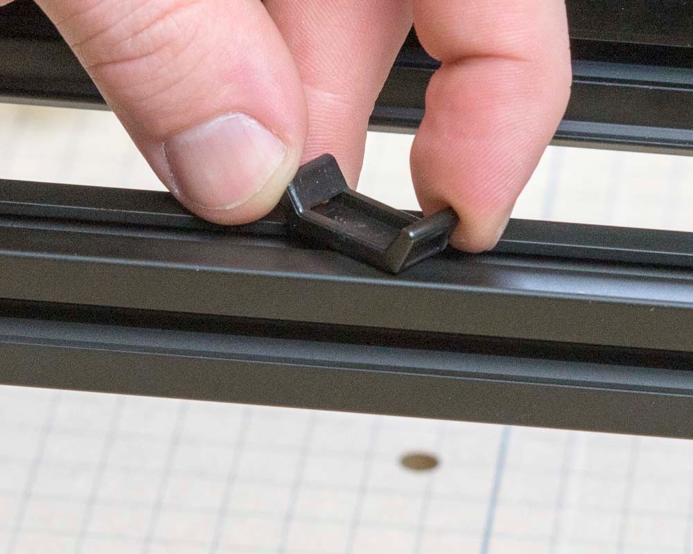
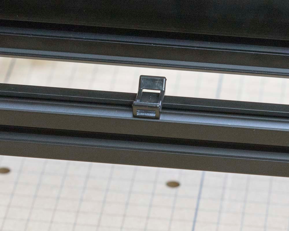
Place 2 zip tie mounts on the back side of the aluminum extrusion that the drag chain is resting on. Place 1 at the far end of the extrusion near the right-side Y rail, and the other about 12 inches toward the center of the machine. These zip tie mounts will hold the Y2 (right side) motor cable.


Place the remaining 3 zip tie mounts on the top of the drag chain extrusion, evenly spaced from the end of the drag chain all the way to the Y1 (left side) motor.
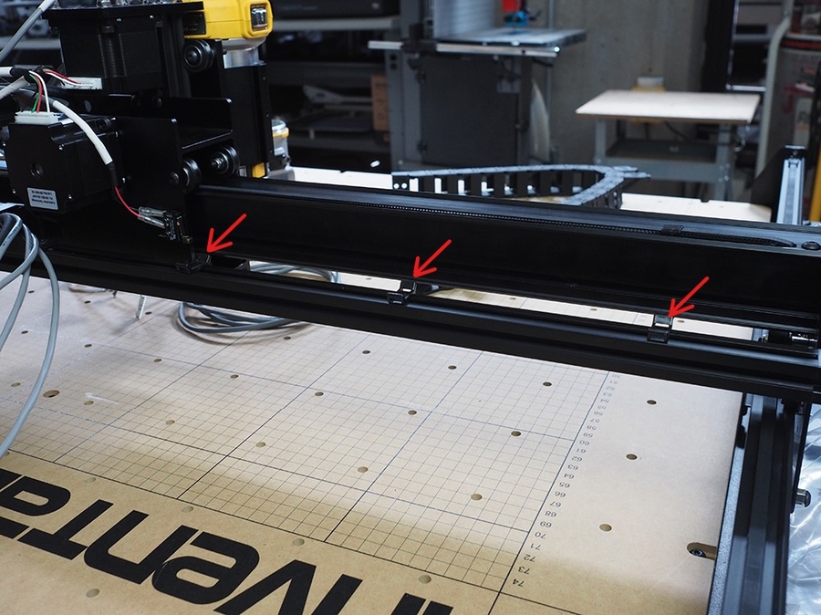


Plug in Y2 stepper motor cable (30679-11) and guide it across the rear of the aluminum extrusion and secure it to the zip tie mounts with zip ties.


Gather up all the wires from the end of the top drag chain and the Y2 stepper motor. Zip tie them to the remaining 3 zip tie mounts.
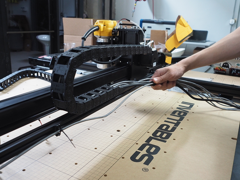

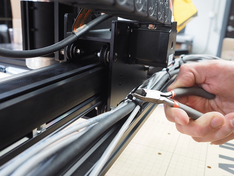
Connect the Y1 axis motor cable and homing switch cable. Per the same process as above.


Attach the Y Axis Drag Chain
1000mm Drag Chain Kit
SKU
Name
Qty
Drag chain
1
M5x12mm Flat Head Screw
2
30265-10
M5 Nyon Lock Nut
2
Using a small flat head screwdriver, open up the drag chain links just like in the previous step. Place M5x12mm flat head screws through the drag chain link and bracket, and e M5 nylon lock nuts. Use a 3mm hex key and 8mm wrench to tighten.

Ensure that the drag chain is correctly oriented, and that the open links are towards the outside of the machine.

Gather up all wires from the X axis drag chain and Y1 motor and homing switch cables.

Once all of the cables are placed in the drag chain, snap all of the drag chain links closed.


Wrap the drag chain under such that the cables are facing towards the front of the machine.

Attach Lower Drag Chain Bracket (optional)
You can skip this step if you purchased the Sideboard kit.Lower Drag Chain Bracket (Optional- skip this if you have the Sideboard Kit)
1000mm Drag Chain Kit
SKU
Name
Qty
30527-06
Long Drag Chain Bracket
1
25286-31
M5x6mm Button Head Screw
1
26016-03
M5 post-assembly tee nut
1
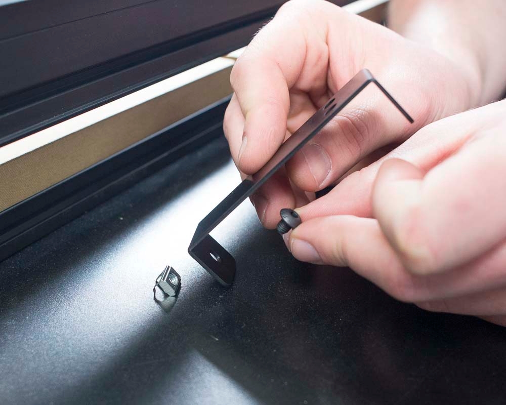
Attach the drag chain bracket to the aluminum extrusion frame under the wasteboard using the M5x6mm button head cp screw and post-assembly insertion nut. This bracket can be installed in the gap between the acrylic stiffeners.
Last updated
Was this helpful?