X-Carriage
In this section we’ll be assembling the X-Carriage. This carriage carries the components for moving the X axis as well as the Z axis.

Smooth Idler Wheels

Core Components Kit
SKU
Name
Quantity
30545-01
X Carriage Extrusion
1
30552-05
Flat Head Screw M5 x 35
2
25312-23
Aluminum Spacer 5.1mm ID 9.5mm OD 9.5mm LG
2
30265-09
Nylon Insert Lock Nut M5
2
9mm Belt and Motor Kit
SKU
Name
Quantity
25197-10
Smooth Idler Pulley Assembly
2
25287-12
M5 Flat Washer
4

Insert an M5x35 flat head screw into one of the countersunk holes in the X-Carriage.


Put an aluminum spacer on the screw followed by an idler wheel, two M5 flat washers and a nylon locking nut. Make sure that the side of the wheel with the recessed bearing faces away from the aluminum spacer (the washers and nylon lock nut will sit inside the pulley), similar to the Y axis plates. Use a 3mm hex key and 8mm wrench to tighten the assembly.


Be sure to include (2) washers before installing the nut.
Repeat this process for the other countersunk hole. Your carriage should now look like this:

Fixed V-Wheels
Core Components Kit
SKU
Name
Quantity
25286-43
Button Head Cap Screw M5 x 25
4
25287-12
M5 Flat Washer
4
25203-01
V Wheel Assembly
4
30265-09
Nylon Insert Lock Nut M5
4
This process is similar to attaching the fixed V-Wheels on the gantry side plates.
Place an M5x25mm button head cap screw through the hole the opposite side of the idler pulleys we just installed, per the image below.

Next, add an M5 washer onto the screw inside of the carriage.

Finally, place the v wheel and M5 nylon lock nut on the screw. Tighten with a 3mm hex key and 8mm wrench.

Repeat this process for the other 3 holes on the lower side of the X carriage. Note that on this side of the X carriage there are 2 flanges outside of the rectangular frame, whereas the opposite side has 1. Ensure that the v-wheels are all inside of the carriage and that they are snug. When complete, your X carriage should look like the below picture.

If damaged during assembly, you can find additional Dual Bearing V-Wheels in the Spare Parts Kit.
Adjustable V-Wheels
Core Components Kit
SKU
Name
Quantity
25286-49
Button Head Cap Screw M5 x 30
4
25195-07
Short Eccentric Spacer
4
25287-12
M5 Flat Washer
4
25203-01
V Wheel Assembly
4
30265-09
Nylon Insert Lock Nut M5
4
Begin by placing a short eccentric spacer (25195-07) on an M5x30mm screw, then place the screw and spacer through one of the 4 remaining holes on the X carriage for the adjustable v-wheel. Make sure that the circular part of the spacer is facing the carriage and fits into the hole on the plate.

Place an M5 Flat Washer on the screw inside the carriage.

Then, place a v-wheel onto the screw.

Finally, add the M5 nylon lock nut on the end of the screw, then tighten with a 3mm hex key and 8mm wrench.

Repeat this process for the remaining v-wheels. When complete, your carriage should look like this:

Stepper Motor

Core Components Kit
SKU
Name
Quantity
25285-54
Socket Head Screw M5 x 10
4
9mm Belt and Motor Kit
SKU
Name
Quantity
25311-10
Stepper Motor - NEMA 23
1
Place the motor on the X-Carriage with the white connector facing the end of the X carriage that has 2 flanges, per the image below. Use a 4mm hex key to secure the motor in place using the threaded holes on the carriage. Note: there may be a small gap between the motor and the carriage due to the heads of the M5x35mm flat head screws that hold the smooth idlers. Tighten the screws in an alternating pattern to ensure that they are evenly secured.


Drag Chain Bracket

1000mm Drag Chain Kit
30527-05
Drag Chain Bracket
1
25286-44
Button Head Cap Screw M4 x 10
2
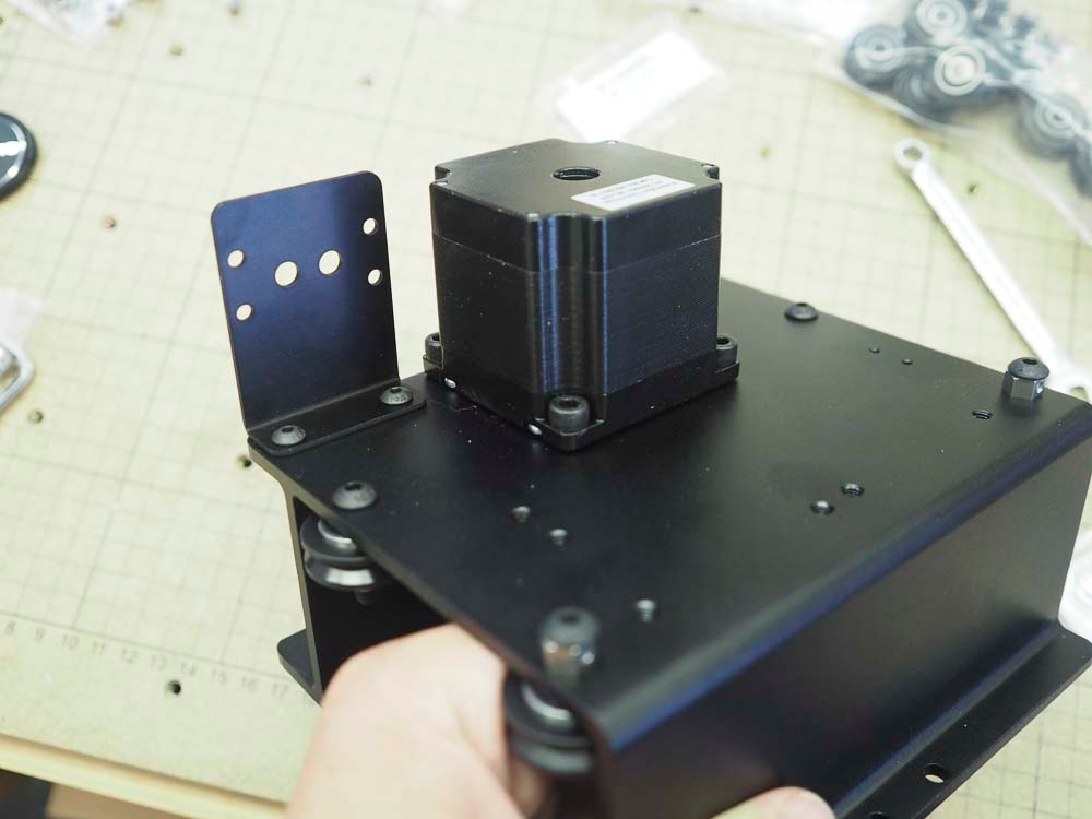
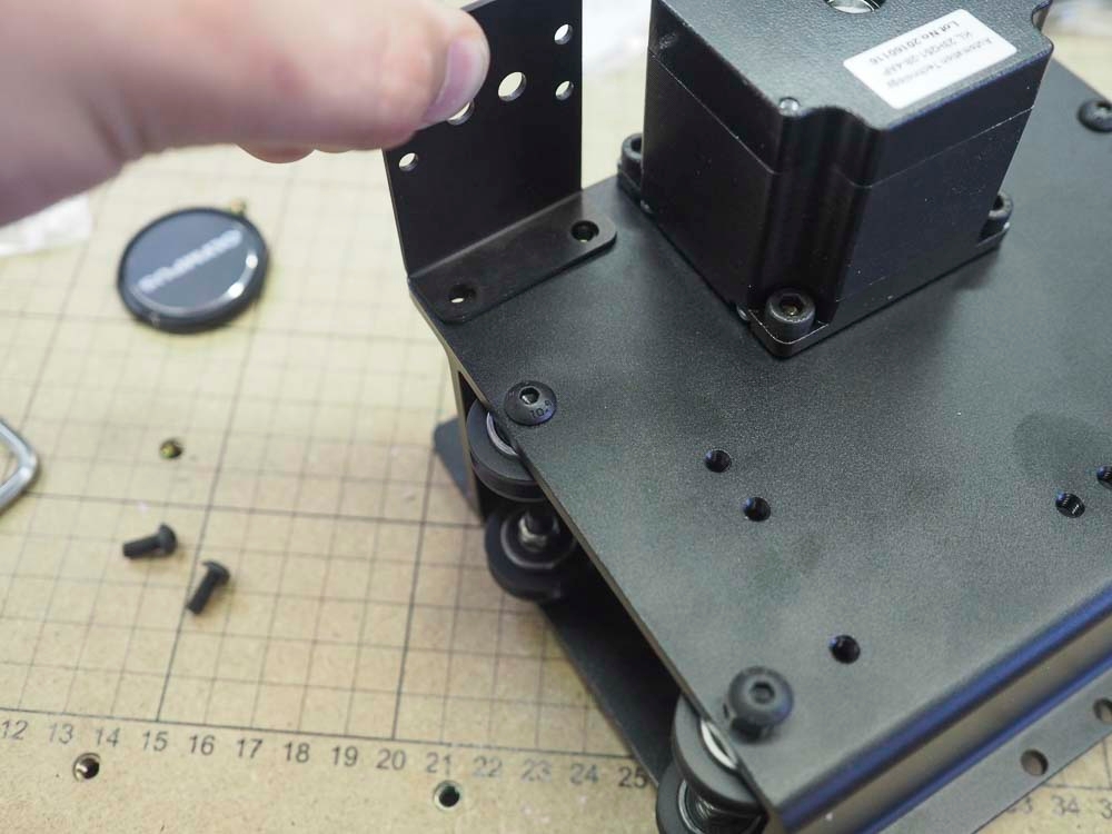
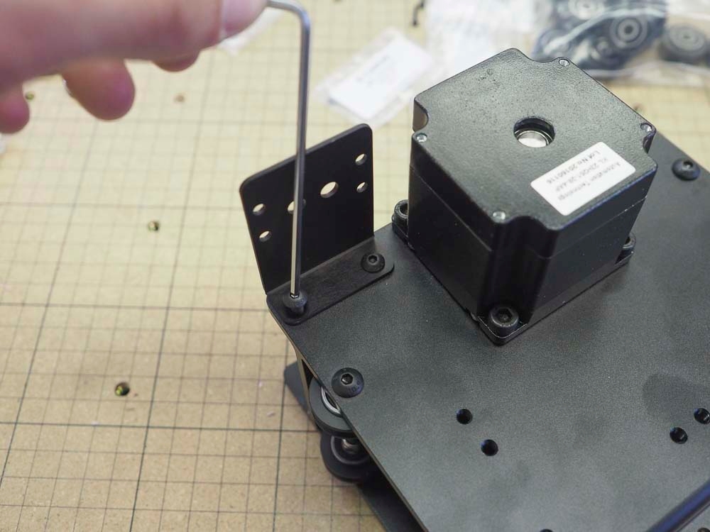
Attach Drag Chain Bracket to X-Carriage
Insert 2x M4x10mm button head screws through the drag chain bracket into the X carriage in the tapped holes beside the motor we just installed. Use a 2.5mm hex key and tighten the bracket to the X carriage, where the bottom of the bracket is flush with the X carriage flange as pictured below. You will install the drag chain later on.


Last updated
Was this helpful?