Loading...
Loading...
Loading...
Loading...
Loading...
Loading...
Loading...
Loading...
Loading...
Loading...
Loading...
Loading...
Loading...
Loading...
Loading...
Loading...
Loading...
Loading...
Loading...
Congratulations! You’ve just taken one of your first steps into the world of 3D Carving! This guide will take you through the steps of building your very own X-Carve 3D Carver! We’ve tried to make it as easy as possible to get you from unpacking your parts to carving. We’ve laid out the instructions starting from the bottom of the machine to the top, and we will cover everything from machine assembly to computer setup.
Building your X-Carve is the first step in becoming a CNC expert. While you are building your machine you will learn about how and why the machine works, and these discoveries will create a strong foundation for you to build on as your hobby or business grows.
If you purchased a tool kit with your machine, most of these should be included with the exception of power tools
7mm wrench or socket
8mm wrench or socket
10mm wrench or socket
13mm wrench
5.5mm or 7/32” wrench or socket
1.5mm hex key
2mm hex key
2.5mm hex key
3mm hex key
4mm hex key
Drill driver with 5mm hex bit
1000mm Rail Kit
SKU
Name
Quantity
25281-10
T-Slot Nut M5 Pre-Assembly
8
26018-01
Extrusion Bracket (Gusset)
4
30558-02
X-Carve Label
1
26049-02
Aluminum Extrusion 20mm × 20mm Black 1000mm Lg
2
26049-04
Aluminum Extrusion 20mm × 20mm Black 958mm Lg
2
25142-11
MakerSlide 1000mm Tapped Black
2
30678-03
MakerSlide Extra Wide 1000mm Tapped Black
1
25286-36
Button Head Cap Screw M5 x 10
8
Homing Switch Kit
SKU
Name
Quantity
30557-02
Microswitch
3
26016-03
Post-Assembly M5 T-Slot Nuts
2
30682-07
Home Switch Cable Assembly 95"Lg X-Limit
1
30682-08
Home Switch Cable Assembly 50"Lg Y-Limit
1
30682-09
Home Switch Cable Assembly 95"Lg Z-Limit
1
25312-25
Spacer 5.1mm ID 9.5mm 10.5mm Lg Aluminum
2
25284-12
Hex Nut M2x0.4
2
30265-07
Hex Nut M3 Nylon Locking
1
25285-56
Socket Head Screw M2 x 10
2
25285-57
Socket Head Screw M2 x 14
4
25285-44
Socket Head Screw M3 x 20
1
25285-51
Socket Head Screw M5 x 16
2
30555-03
Washer, Split Lock M2 Stainless
6
Drag Chain Kit
SKU
Name
Quantity
30527-05
Drag Chain Bracket
2
30527-06
Drag Chain Bracket
1
30680-01
Zip Tie Mount
5
26016-03
T-Nut M5 Post Assembly
5
30681-01
Drag Chain Support Arm
2
30331-13
Drag Chain 18x25 21 Links w/ Custom Ends
2
25986-03
Cable Tie 4" (100 Pack)
1
26049-09
Extrusion T-Slot 20x20 x 1000mm Tapped
1
25286-44
Button Head Cap Screw M4 x 10
4
25286-31
Button Head Cap Screw M5 x 6
1
25286-46
Button Head Cap Screw M5 x 14
2
30554-06
Flat Head Cap Screw M5 x 10
4
30554-07
Flat Head Cap Screw M5 x 12
6
30265-08
Nylon Insert Lock Nut M4
2
30265-10
Nylon Insert Lock Nut M5
6
1000mm Sideboard Kit
SKU
Name
Quantity
30684-01
Extrusion Connection Bracket
2
25281-13
T-Slot Nut M5 Pre-Assembly
21
26018-01
Cast Corner Bracket, Clear
4
30517-13
Threaded Insert M5
15
30685-03
Side Board, X-Carve 1000mm
1
26049-10
Extrusion T-Slot 20x20 x 250mm
2
26049-04
Extrusion T-Slot 20x20 x 958mm
2
25286-34
Button Head Cap Screw M5 x 8
8
25286-37
Button Head Cap Screw M5 x 10
8
25286-41
Button Head Cap Screw M5 x 12
5
25286-47
Button Head Cap Screw M5 x 14
12
Spindle and Mount
SKU
Name
Quantity
30845-01
Makita RT0701C Router
1
30839-01
Makita Spindle Mount
1
30558-04
X-Carve Label
1
30831-01
X-Carve Spindle Mount Hardware Subassembly
1
25285-55
Socket Head Cap Screw - M4 x 16
3
25286-45
Button Head Cap Screw, M5 x 16
2
30662-01
Collet Adapter
1
NEMA 23 Cable Kit
SKU
Name
Quantity
30679-12
Stepper Motor Cable Assemblies
1
30679-11
Stepper Motor Cable Assemblies
1
30679-09
Stepper Motor Cable Assemblies
1
30679-10
Stepper Motor Cable Assemblies
1
9mm Belt and Motor Kit
SKU
Name
Quantity
30858-01
9mm Belt Clip
6
25197-10
Smooth Idler - 9mm Belt - qty 1
6
25311-10
X-Carve Upgrade Motor w/ Pulley Assembly - KL23H265-28-4AP-1; qty 3
1
26053-04
GT2 Belting - Open Ended
1
30677-04
9mm Belt Sleeve
1
25287-13
FLWM5S - Flat Washer M5 DIN125 Steel - Qty 12
1
Core Components Kit
SKU
Name
Quantity
30525-01
Gantry Side Plate
2
25195-07
Eccentric Spacer
8
25203-01
Dual Bearing V-Wheel Kit
16
25312-23
Aluminum Spacers
6
25285-52
SHMSM516S - Socket Head Screw M5 x 16 Steel/Black - Qty 8
8
25285-53
SHMSM520S - Socket Head Screw M5 x 20 Steel/Black - Qty 4
4
25285-54
SHMSM510SB - Socket Head Screw M5 x 10 Steel/Black - Qty 4
4
25286-XX
BHCSM508S - Button Head Screw M5 x 8 Steel/Black - Qty 6
6
25286-XX
BHCSM512S - Button Head Screw M5 x 12 Steel/Zinc - Qty 4
4
25286-43
BHCSM525S - Button Head Screw M5 x 25 Steel/Black - Qty 11
11
25286-49
BHCSM530S - Button Head Screw M5 x 30 Steel/Black - Qty 12
12
25287-11
Flat Washer
1
25287-XX
FLWM5S - Flat Washer M5 DIN125 Steel/Black - Qty 22
22
30265-XX
Nylon Insert Lock Nut, M5
37
30552-05
Flat Head Socket Cap Screw M5 x 35
2
25281-XX
Pre-Assembly T-Slot Nuts
1
30545-01
X Carriage Extrusion
1
30837-01
Marketing Packet
1
30837-04
V-Bit Postcard
1
30784-02
1/8" Bit Set for V-Carving
1
30891-01
HDPE Sample
1
Dust Control Kit
SKU
Name
Quantity
30748-02
Dust System Hose Mounting Poles
1
30748-01
Dust System Hose Mounting Poles
1
30750-01
Dust Hose
1
30741-01
X-Carve Dust Control System Accessories
2
30749-01
Z-Probe Relocation Bracket
1
30751-01
Dust Hose Fittings
1
30752-01
Dust Shoe Alignment Label
2
30799-02
Dust Shoe Subassembly
1
30804-01
Dust Shoe Right Arm Subassembly
1
30804-02
Dust Shoe Left Arm Subassembly
1
30756-01
Z-Probe Relocation Bracket Hardware Kit
1
30755-01
Dust Hose Grounding Strap Kit
1
30754-01
Dust Shoe Support Assembly Hardware Kit
1
30753-01
Dust Shoe Hardware Kit
1
30746-01
Hose Clip
5
30747-01
Pole Base
1
30743-01
Dust Shoe T-Slot Bracket
2
Z Axis Upgrade Kit
SKU
Name
Qty
30885-01
Z Axis Assembly
1
30885-01
X-Carve Z Upgrade Hardware Subassembly - M5 Tee Nut qty 4;Button Head Cap Screw M5x10 qty 4;M5 x 16 Socket Head Screw qty 4M5 Washer qty 4
1
30872-01
Dust Shoe Knobs
2
30844-01
2" Riser Rev 3
4
30874-01
Riser Upgrade Hardware Subassembly:M5 x 14 Socket Head Screw - qty 10M5 x 10 Socket Head Screw - qty 8M5 Lock Nut - qty 1M5 Tee Nut - qty 8
1
30870-01
Acrylic Stiffener
8
30873-01
Dust Cover / Stiffener Hardware Subassembly - M5 twist t-slot nut qty 48 M5 x 8mm BHCS qty 48
1
30837-05
Clear Inventables Sticker
1
30749-01
Z-Probe Relocation Bracket
1
30756-01
Z-Probe Relocation Bracket Hardware Kit
1
Spare Parts Kit
SKU
Name
Qty
30611-03
Z-Probe Wiring Harness
1
26053-04
GT2 Belting - Open Ended 9mm
1
30557-02
Microswitch
1
25203-01
Dual Bearing V-Wheel Kit
1
25281-02
Pre-Assembly T-Slot Nuts M5
10
26016-03
Post-Assembly T-Slot Nuts M5
1
30901-02
Post Assembly T-Slot Nuts (twist lock) M5
4
25286-34
M5 x 8mm Button Head Cap Screw
8
25286-37
M5 x 10mm Button Head Cap Screw
8
25286-55
M5 x 12mm Button Head Cap Screw
8
30681-01
Drag Chain Support Arm
1
25312-25
Aluminum Spacers
1
30872-01
Upgrade Dust Shoe Knobs
1
30741-01
Dust Control System Spindle Insert Plate
1
30889-01
Makita Replacement Brush
2
This is a do-it-yourself 3D carving kit: the more time and attention you put into assembling your machine, the better it will perform. If you run into any trouble during assembly or carving you can find further help from the wonderful community on the forum, our support center which is continuously growing with articles and tutorials, and as always you can reach our Customer Success team through our or by emailing us at help@inventables.com.
The X-Carve is open-source hardware. We have 3D models and drawings available in a GitHub repository .
A Computer capable of running Easel: You can check our System Requirements
Earlier models of the Post-November 2021 X-Carve may contain slightly different configurations and SKUs than what you see listed below. If you have any questions or concerns about the materials and components received with your order, please reach out to our Customer Success team at and an agent will follow up to assist you.
Only X-Carve Kits shipped after 6/06/2022 include the Spare Part Kits. X-Carve Kits shipped before this date will not include the Spare Parts Kit. If you have any concerns about the materials and components included with your order, please reach out to our Customer Success team at .
The X-Carve Kit may include extra hardware and leftover screws at the end of the build. If you have any questions or concerns about left-over components after assembly, please feel free to contact our Customer Success team at .
1000mm Rail Kit
SKU
Name
Quantity
25281-10
T-Slot Nut M5 Pre-Assembly
8
26018-01
Extrusion Bracket (Gusset)
4
26049-02
Aluminum Extrusion 20mm × 20mm Black 1000mm Lg
2
26049-04
Aluminum Extrusion 20mm × 20mm Black 958mm Lg
2
25286-36
Button Head Cap Screw M5 x 10
8
Modular Waste Board Kit
SKU
Name
Quantity
30887-01
Waste Board MDF Slat
4
30887-02
MDF Back Board
1
25300-03
T Slot Extrusion
3
30517-18
Threaded Inserts
200
26047-04
Aluminum Extrusion, 20mm x 20mm 898mm Lg
2
26018-01
Extrusion Bracket (Gusset)
4
30888-03
Waste Board Hardware Kit
1
25281-16
M4 Tee Nut
9
In this section you'll be assembling the work area of your machine.
1000mm Rail Kit
SKU
Name
Quantity
26018-01
Extrusion Bracket (Gusset)
1
26049-02
Aluminum Extrusion 20mm x 20mm Black 1000mm long
1
26049-04
Aluminum Extrusion 20mm × 20mm Black 958mm long
1
25286-37
M5x10mm Button Head Screw
2
25281-15
M5 Tee Nut
2
Insert the M5x10mm Button Head Screws into the extrusion bracket as shown. Loosely thread a tee nut onto the end of each screw. On the side of the extrusion bracket (gusset) that has 2 holes, thread the M5x10mm Button Head Screw through the hole that's furthest from the corner.
Slide the extrusion bracket (gusset) onto the shorter of the 2 extrusions (26049-04 958mm long
Slide the longer of the 2 black extrusions (26049-02, 1000mm long) through the other side of the extrusion bracket (gusset).
Use one waste board extrusion and one waste board tee track to set the correct location of the 1000mm rail. Then use a 3mm hex key to secure the extrusion bracket (gusset) to each extrusion.
Modular Waste Board Kit
SKU
Name
Quantity
30888-01
Waste Board Hardware Subassembly
M5x12mm Button Head Screw
3
M5 Tee Nut
3
Thread one screw into each nut, as shown below.
Slide screws with tee nuts into the top extrusion slots, as shown. Two screws should be slid into the 1000mm extrusion, and 1 screw should be slid into the 958mm extrusion. You will have to slide it into the 958mm extrusion from the back.
Modular Waste Board Kit
SKU
Name
Quantity
30888-01
Modular Waste Board Slat
1
Align the MDF slat with the edges of the base extrusions, then secure it in place by tightening the three screws.
Modular Waste Board Kit
SKU
Name
Quantity
26047-04
Aluminum Extrusion, 20mm x 20mm 898mm Long
2
M5x12mm Button Head Screw
3
M5 Tee nut
3
Loosely thread 3 M5x12mm Button Head Screws with 3 M5 Tee Nuts. Slide 2 of the Screws and Tee Nuts through one of the 898mm extrusions and 1 through the other extrusion as picture below.
Coming from the left side, slide the extrusion with screw and tee nut into the middle of the waste board slat as pictured below, ensuring that it is touching the black extrusion on the other side of the waste board slat.
Slide the other extrusion with the 2 screws and tee nuts along the top side of the waste board slat, ensuring the silver extrusion is perpendicular to the black extrusion on the right side. Tighten the screws to the waste board slats using a 3mm hex key.
Modular Waste Board Kit
SKU
Name
Quantity
25300-03
Tee Track
3
30888-01
M4 x 10 Button Head Cap Screw
6
30888-01
M4 Nylon Nut
6
30888-01
Oversize Washer
6
Each section of tee track has 5 holes drilled in it. We will be installing oversized washers on the second and fourth holes, as shown below.
Use a 2.5mm hex key to insert the M4 x 10mm button head screw into the appropriate hole of the tee track.
Add an oversized washer onto the screw, then an M4 Nylon nut.
Tighten using your 2.5mm hex key with a 7mm wrench. Repeat this for the second and fourth hole in each of the three tee tracks.
Core Components Kit
SKU
Name
Quantity
30525-01
Gantry Side Plate
2
Now that you’ve built the work area, we’ll guide you through the construction of the main carriages and rails of the X-Carve. We’ll start by assembling the plates and carriages of the Y and X axes, then we’ll put it all together to form the gantry.
The gantry side plates hold various wheels, brackets, and motors. They are joined by the main gantry rail included in your kit. There are a number of holes and slots on the plates. Below is a diagram of the plate. Note that when assembled, both plates will form mirror images of each other, though the beveled edge will always face up and towards the front of the machine with the holes for makerslide on top. We’ll start by assembling the righthand plate.
Core Components Kit
SKU
Name
Quantity
25286-43
Button Head Cap Screw M5 x 25
4
25287-12
M5 Flat Washer
4
25203-01
V Wheel Assembly
4
30265-09
Nylon Insert Lock Nut M5
4
First, we’ll attach the fixed v-wheels to the carriage. Insert the M5x25 bolt into one of the smaller v-wheel holes, then put on an M5 flat washer followed by a v-wheel. Use an M5 nylon lock nut to secure the assembly. Tighten the nut until secure using a 3mm hex key on the bolt and an 8mm wrench on the nut.
Repeat this for the other v-wheel on the right-hand plate, and then repeat the process for the left hand plate on the other side. You should now have two mirrored plates that look like this:
Core Components Kit
SKU
Name
Quantity
25286-49
Button Head Cap Screw M5 x 30
4
25195-07
Short Eccentric Spacer
4
25287-12
M5 Flat Washer
4
25203-01
V Wheel Assembly
4
30265-09
Nylon Insert Lock Nut M5
4
Attaching the adjustable v-wheels is a bit more complicated, though you won’t have to adjust them until later in the assembly. These v-wheels are adjusted by means of a short eccentric spacer (25195-07) that rests inside a larger hole on the plate. By turning the spacer, the distance between the v-wheels can be adjusted just enough to make sure that they are snug on the Makerslide rail. For the moment you’ll want to install the spacers in the ‘open’ position, that is, rotated so that the adjustable v-wheel is as far from the corresponding fixed v-wheel as possible.
Begin by placing a short eccentric spacer (25195-07) on an M5x30mm bolt. Be sure that the circular part of the spacer is on the opposite side of the screw head, per the below image.
Place the screw and spacer through one of the larger holes on the side plate. Make sure that the circular part of the spacer is facing the plate and fits into the hole on the plate. Place an M5 washer and v-wheel onto the bolt.
Secure the assembly with an M5 nylon lock nut using a 3mm hex key and 8mm wrench. Make sure not to over-tighten the assembly.
Now you can repeat this for the other side of the plate. You should have two mirrored plates that look like this:
Core Components Kit
SKU
Name
Quantity
25286-49
Button Head Cap Screw M5 x 30
4
25312-23
Aluminum Spacer 5.1mm ID 9.5mm OD 9.5mm LG
4
30265-09
Nylon Insert Lock Nut M5
4
9mm Belt and Motor Kit
SKU
Name
Quantity
25197-10
Smooth Idler Pulley Assembly
4
25287-13
M5 Flat Washer
8
These wheels ensure that the belt is held tightly against the motor pulley once they are installed. They are installed with aluminum spacers as they need to be aligned with the center of the Makerslide rails. We show both wheels being attached at once for illustrative purposes, though as long as they’re in the right places, assemble them in whichever order you want.
To attach the smooth idler wheels, begin by putting an M5x30 bolt through the appropriate hole on the plate. Slide an aluminum spacer onto the bolt.
Place an idler wheel onto each bolt. Make sure that the side of the wheel with the recessed bearing is facing away from the plate.
Add two M5 washers to on top of each wheel.
Thread an M5 nylon lock nut onto each bolt and secure with a 3mm hex key and 8mm wrench. The nut isn’t the most accessible with the flange of the idler wheel in the way, so you may have to angle the wrench.
Repeat this for the other plate. You should now have two mirrored plates that look like this:
9mm Belt and Motor Kit
SKU
Name
Quantity
25311-10
Stepper Motor - NEMA 23
2
In this step, we’ll be attaching the motors to the Y plates. The motor pulleys are already attached to the shafts of the motors so you won’t have to worry about attaching or adjusting them.
Core Components Kit
SKU
Name
Quantity
25285-52
Socket Head Screw M5 x 16
8
30265-09
Nylon Insert Lock Nut M5
8
First, position the motor hub in the large hole on the gantry plate on the opposite side of the v-wheels and idler pulleys we just installed. Make sure that the white socket for the electrical connection is facing the rear of the gantry plate (it should be facing away from the angled part of the side plate). Note the orientation in the image below.
If you ordered your X-Carve before March 28 2022 you will use M5x16mm screws for the lower 2 stepper motor mounting holes, and M5x20mm screws for the upper 2 stepper motor mounting holes.
Insert the socket-head cap screws through the stepper motor holes and side plate, then thread on M5 nylon lock nuts to each. See image below.
Note: installing the M5x16 screws on the bottom may be a bit more difficult due to proximity of the idler pulleys. Flip the assembly over so that it is resting on the back side of the motor.
From this position, you can take an 8mm wrench and hold the nylon lock nut in place while you thread the socket head screw from the bottom.
Loosely tighten each bolt with a 4mm hex wrench, holding the nut with an 8mm wrench. Go back and secure each bolt until snug.
Repeat this process for the other side plate. You should now have two mirrored plates that look like this:
Locate 1x drag chain bracket, 2x M4 x 10 button head cap screws and 2x M4 nylon lock nuts. The drag chain brackets and hardware should be included in a bag that is shrink-wrapped to the drag chain links and rails.
1000mm Drag Chain Kit
30527-05
Short Drag Chain Bracket
1
25286-44
Button Head Cap Screw M4 x 10
2
30265-08
Nylon Insert Lock Nut M4
2
To attach the drag chain mount to the left plate, take 2x M4x10mm screws and put them through their respective holes on the drag chain bracket and plate. Take 2x M4 nylon lock nuts and secure the drag chain bracket with a 7mm wrench and a 2.5mm hex key. Keep in mind that this is for the left plate only, the other drag chain bracket of this type is for the x-carriage.
Z Axis Kit
SKU
Name
Qty
30870-01
Stiffener
8
30873-01
Stiffener Hardware Kit
1
** The stiffeners are packed into the bottom of the Z-axis kit box and all the hardware bags along with the raisers are right next to it. Z-Axis is wrapped in foam and placed on top of the stiffeners, risers and hardware.
Rail Kit
SKU
Name
Qty
25142-11
MakerSlide
2
Stiffener Hardware Kit
SKU
Name
Qty
M5x8mm Button Head Screw
48
M5 Tee Nut Twist On
48
30870-01
Stiffener
8
Remove protective paper from both sides of all 8 stiffeners
Using a 3mm hex key, install 6 M5 x 8 Button head screws and 6 M5 twist on tee nuts onto each stiffener, as shown below. Be sure to thread the screws on the top in the opposite direction as below t allow the stiffener to attach to the base and Y axis makerslide.
Slide the twist on tee nuts at the base of each stiffener into the wasteboard frame as shown below. Once all twist on tee nuts are in the waste board extrusion channel, tighten each of the M5x8mm button head screws with a 3mm hex key until the stiffener is tight to the MDF and waste board extrusion.
Repeat this process, installing 4 stiffeners on each side of the waste board.
Once all stiffeners have been installed and are tight, double check that your X-Carve looks like the below gif, and that on twist on tee nuts on the top sides of each stiffener are on the outsides of the machine.
Rail Kit
SKU
Name
Qty
25142-11
MakerSlide
2
Orient the Makerslide such that the wide edge with 2 tee nut channels faces the middle of the machine, and the opposite wide edge with a single channel is facing the outside of the machine. Note the orientation of the Makerslide in the below image (Y1 axis, left side of the machine.
Note the tee nut channel on the outside will be on the bottom per the below gif.
Repeat this process on the other side with the other Makerslide, note the orientation of the makerslide in the image below (Y2 axis, right side).
Modular Waste Board Kit
SKU
Name
Quantity
M4 Tee Nut
3
M4x8mm Button Head Screw
3
Insert one M4 tee nut into the top slot of each of the 3 extrusions that run side to side.
Place the tee track on top of the extrusions and thread an M4 x 8mm screw through the tee track and into each tee nut. Start with the black extrusion in the front. You may need to move the silver extrusions in order to line up the tee nuts with the holes in the tee track.
Slide the tee track extrusion to be lined up against the MDF slat.
Modular Waste Board Kit
SKU
Name
Quantity
25281-15
M5 Tee Nut
6
M5x12mm Button Head Screw
6
Thread 3 M5x12 Button Head Screws onto 3 M5 Tee Nuts. Slide 2 of the screws/tee nuts onto the rear extrusion and 1 onto the middle extrusion as pictured below. Slide the remaining 2 tee nuts onto the black front extrusion.
Align the 2 screws on the rear silver extrusion to the spacing on the waste board slat, and slide the slat onto the screws.
Align the front of the waste board slat to the two tee nuts in the black extrusion. Thread two M5 x 12mm button head screws through that waste board slat and into the tee nuts.
Slide the M5 screw on the center extrusion into the slot on the MDF slat.
Slide the MDF slat against the tee track. We will tighten these screws at the end, for now it is best to leave them a bit loose.
Thread the last M5x12mm button head screw with the tee nut, and slide it onto the center extrusion. Slide the screw/tee nut into the final slot on the board slat and tighten until snug using a 3mm hex key.
Modular Waste Board Kit
SKU
Name
Quantity
M4 Tee Nut
3
M4x8mm Button Head Screw
3
Following the process from earlier, insert one M4 tee nut into the top slot of each of the 3 extrusions that run side to side. Place the tee track on top of the extrusions and thread an M4 x 8mm screw through the tee track and into each tee nut. Start with the black extrusion in the front.
Slide the tee track extrusion to be lined up against the MDF slat as pictured below.
Modular Waste Board Kit
SKU
Name
Quantity
25281-15
M5 Tee Nut
6
M5x12mm Button Head Screw
6
Thread 3 M5x12 Button Head Screws onto 3 M5 Tee Nuts. Slide 2 of the screws/tee nuts onto the rear extrusion and 1 onto the middle extrusion as pictured below. Slide the remaining 2 tee nuts onto the black front extrusion.
Align the 2 screws on the rear silver extrusion to the spacing on the waste board slat, and slide the slat onto the screws.
Align the front of the waste board slat to the two tee nuts in the black extrusion. Thread two M5 x 12mm button head screws through that waste board slat and into the tee nuts.
Thread the last M5x12mm button head screw with the tee nut, and slide it onto the center extrusion. Slide the screw/tee nut into the final slot on the board slat and tighten until snug using a 3mm hex key.
Modular Waste Board Kit
SKU
Name
Quantity
M4 Tee Nut
3
M4x8mm Button Head Screw
3
Following the process from earlier, insert one M4 tee nut into the top slot of each of the 3 extrusions that run side to side. Place the tee track on top of the extrusions and thread an M4 x 8mm screw through the tee track and into each tee nut. Start with the black extrusion in the front.
Slide the tee track extrusion to be lined up against the MDF slat as pictured below.
Modular Waste Board Kit
SKU
Name
Quantity
25281-15
M5 Tee Nut
5
M5x12mm Button Head Screw
5
Thread 3 M5x12 Button Head Screws onto 3 M5 Tee Nuts. Slide 2 of the screws/tee nuts onto the FRONT extrusion and 1 onto the middle extrusion as pictured below. Slide the remaining 2 tee nuts onto the REAR extrusion. Note, this is the opposite process from previous steps.
Slide 2 M5 tee nuts into the silver extrusion, aligning the spacing with the holes in the waste board slat.
Align the 2 screws on the front black extrusion to the spacing on the waste board slat, and slide the slat onto the screws.
Secure the waste board slat to the extrusion using 2 M5x12mm button head screws threaded onto the tee nuts as pictured below.
Modular Waste Board Kit
SKU
Name
Quantity
26018-01
Extrusion bracket (gusset)
1
M5 Tee Nut
3
M5x12mm Button Head Screw
1
1000mm Rail Kit
26049-04
Aluminum Extrusion, 20mm x 20mm 958mm Long
1
M5x10mm Button Head Screw
2
Thread 2 M5x10mm button head screws through the extrusion bracket (gusset) onto M5 tee nuts. Slide one side of the extrusion bracket (gusset) onto the 958mm black extrusion per the picture below.
Thread the remaining M5x12mm button head screw onto the remaining tee nut and slide into the top of the 958mm extrusion. Tighten the extrusion bracket (gusset) to the 958mm extrusion using a 3mm hex key, ensuring that the extrusion bracket and extrusion end are aligned per the picture below.
Slide the extrusion bracket attached to the 958mm extrusion onto the 1000mm extrusion that the waste board slats are attached to, per the picture below.
Align the button head screw and tee nut to the hole on the waste board slat.
Slide the extrusion to under the waste board slat.
Align the extrusion with the edge of the MDF slat, and then tighten the M5x12mm screw that secures the waste board slat to the extrusion.
In this section we will install the homing switches and actuators for the X, Y, and Z axes.
1000mm Homing Switch Kit
SKU
Name
Quantity
30557-02
Microswitch
3
25285-57
Socket Head Screw M2 x 14
4
25285-56
Socket Head Screw M2 x 10
2
30555-03
Washer, Split Lock M2 Stainless
6
25285-51
Socket Head Screw M5 x 16
2
26016-03
Post Assembly M5 Tee Nuts
2
25312-25
Aluminum Spacers
2
1000mm Homing Switch Kit
SKU
Name
Quantity
30557-02
Microswitch
1
25285-56
M2x10 Socket Head Screw
2
30555-03
Washer, Split Lock M2 Stainless
2
Place an M2 split lock washer on each M2x10 socket head screw.
There are 2 tapped holes on the top right side of the Z axis assembly. Slide the 2 M2x10mm socket head screws through the holes in the switch. With the actuator facing the front of the machine, use a 1.5mm hex key to secure the switch to the Z axis. Be sure not to over-tighten the screws as it may damage the switch.
1000mm Homing Switch Kit
SKU
Name
Quantity
30557-02
Microswitch
1
25285-57
Socket Head Screw M2 x 14
2
30555-03
Washer, Split Lock M2 Stainless
2
There are 2 tapped holes on the backside of the X carriage for mounting the X axis homing switch.
Place a split lock washer on each of the M2x14mm screws and place through the holes on the switch. With the switch actuator facing away from the motor, tighten the switch to the X carriage using a 1.5mm hex key. Be sure not to over-tighten the screws as it may damage the switch.
1000mm Homing Switch Kit
SKU
Name
Quantity
25285-51
Socket Head Screw M5 x 16
1
26016-03
Post Assembly M5 Tee Nuts
1
25312-25
Aluminum Spacers
1
The actuator for the X axis homing switch will be located on the back side of the X axis Makerslide.
Place the post-assembly M5 Tee Nut in the bottom channel on the backside of the X axis extrusion.
Place the aluminum spacer on the M5x16 socket head screw and tighten it into the post-assembly Tee Nut using a 3mm hex key.
We will set the correct location of this stop when we calibrate the machine.
1000mm Homing Switch Kit
SKU
Name
Quantity
30557-02
Microswitch
1
25285-57
Socket Head Screw M2 x 14
2
30555-03
Washer, Split Lock M2 Stainless
2
Place a split lock washer on each of the M2x14mm screws and place through the holes on the switch. Tighten using a 1.5mm hex key and make sure the switch is installed with the arm hanging downwards.
1000mm Homing Switch Kit
SKU
Name
Quantity
25285-51
Socket Head Screw M5 x 16
1
26016-03
Post Assembly M5 Tee Nuts
1
25312-25
Aluminum Spacers
1
The Y Axis Homing Switch Actuator is installed on the left Y-Axis, approximately 2" from the front of the machine. We will set the correct location of this stop when we calibrate the machine in a later step.
Press the tee nut into the outside channel of the left side extrusion (same side where we installed the homing switch on the Y plate). Place the aluminum spacer on the M5x16 socket head screw and secure it to the tee nut using a 3mm hex key.
Using your hands, squeeze all the waste board parts together such that the waste board slates and t slot extrusions are all touching one another.
Line up the front of each panel with the front edge of the black extrusion. Secure each panel in place.
Tighten the button head screws attached through the waste board slats with a 3mm hex key.
Tighten the button head screws at the center of each waste board slat.
Repeat this for all four of the MDF slats, ensuring that all of the screws attaching the waste board slats are tight and aligned. Using a 2.5mm hex key, tighten the 3 screws on each tee track.
Onto each of the 2 extrusion brackets (gussets), thread 2 M5x10 button head screws onto M5 tee nuts. Slide each extrusion bracket into the ends of the 958mm extrusion and secure using a 3mm hex key, ensuring the bracket is aligned to the end of the extrusion. Insert a tee nut into the top channel of each 958mm extrusion per the image below.
Slide the rear 1000mm extrusion across the back of the machine and onto the angle brackets.
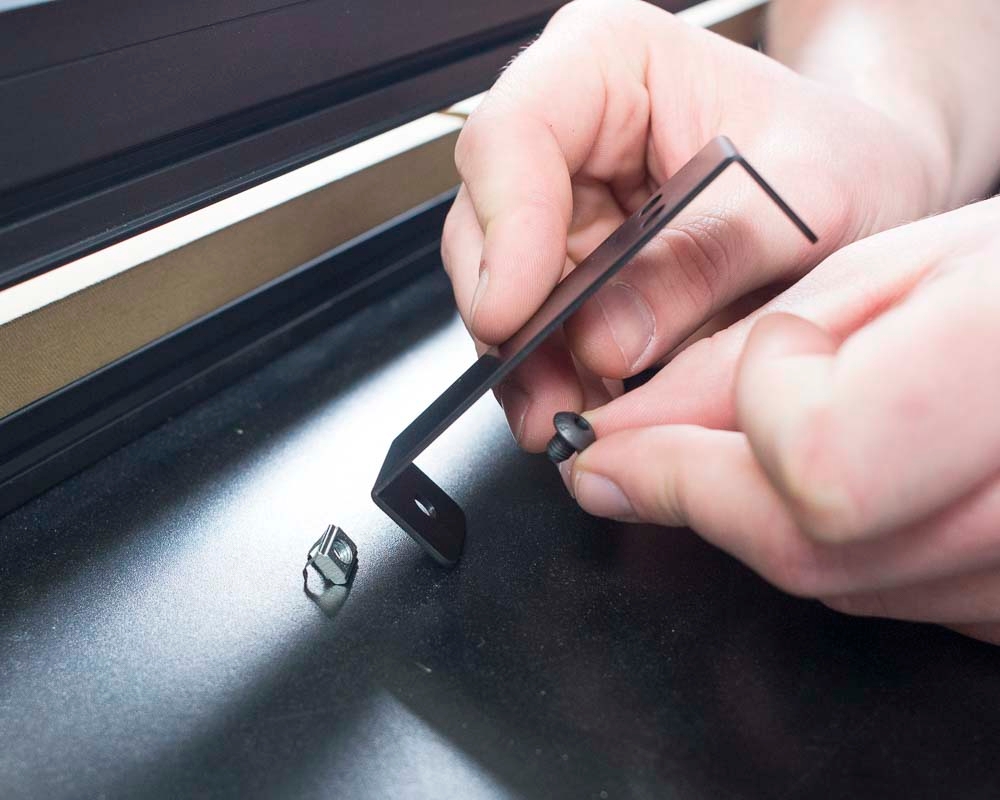
Secure the rear 1000mm extrusion by tightening the angle brackets. Be sure to check that the extrusions are perpendicular to each other and that the extrusion brackets are tight to each extrusion. If centered properly, there should be about a ~1in gap on either end of the extrusion.
Thread 2 M5x10 button head screws through an extrusion bracket and onto M5 twist on tee nuts, per the image below. Repeat for the second extrusion bracket.
Press the extrusion bracket into the corner between the silver and black extrusions at the back of the waste board slats.
Using a 3mm hex key, tighten the screws on the extrusion bracket.
The back section of the waste board should now look like the below picture, and all extrusion brackets should be tightened.
Slide the last 3 M5 tee nuts into the top channel of the rear extrusion.
Place the MDF back board on top of the extrusions, ensuring that the cut outs align with the t tracks on the main waste board. Slide the tee nuts along each extrusion to align with the notches in the back board.
Slide 2 flat washers onto each M5x12mm button head screw.
Using a 3mm hex key, secure the MDF back board to the tee nuts, ensuring that the washers are laying on top of the back board.
You will need to Install the threaded inserts on the back side of the wasteboard in order to use your clamps correctly.
Flip the waste board over so you can access the back side of the waste board slats.
Using a 5mm hex key or drill equipped with the 5mm hex driver bit, install the threaded inserts into the back of the waste board slats into the pre-drilled holes. Be sure not to over tighten the threaded inserts and only install as far as the threaded inserts sitting on top of the MDF.
Thread 2 M5x10 button head screws through an extrusion bracket and onto M5 twist on tee nuts, per the image below. Repeat for the second extrusion bracket.
With the MDF back board towards you, place the extrusion brackets with twist on tee nuts into the outside corners on the center extrusion as pictured below.
Press the extrusion brackets into each corner and ensure they are contacting both the black and silver extrusions.
Using a 3mm hex key, tighten the screws on the extrusion brackets.
Your waste board frame is now complete and should like the below picture.
This section covers mounting the drag chain and wiring.
In this step we will be installing the drag chain support arms through the Y plates and into the remaining threaded holes on the X axis extrusion.
Starting on the left side, position the drag chain support arm with the extrusion mount angling down (as shown). Secure the drag chain support arm through the Y plate and into the X axis Makerslide rail with two M5x12mm button head cap screws. Tighten with a 3mm hex key. Repeat this process for the other side. If you haven't already, tighten the screws that mount the side plate to the Makerslide as well.
Place an M5x14 button head screw through the hole in the plastic support arm and thread it onto the end of the 1000mm extrusion. Repeat this process for the other side and tighten the screws with a 3mm hex key.
Prepare the drag chain lengths by popping open the hinges using a small flat head screw driver.
Using a flat head screw driver, carefully remove the last link of the drag chain on the side where the the link is flipped upside-down from the open links (see below image).
Insert 2 M5 post-assembly tee nuts into the top side near the center of the drag chain extrusion we just mounted to the Y plates. Place the Drag chain link that was removed over the tee nuts oriented such that the circular portion of the end link is facing the right-hand side of the machine. Loosely secure the end link to the post-assembly tee nuts using 2 M5x10mm flat head screws and a 3mm hex key.
If you ordered your machine with a Z-Probe, you can now fasten the Z-Probe barrel connector port and its wire to the x-carriage, otherwise, you can skip this step.
First, open your z-probe kit. Set aside the puck and alligator clip wiring harness for the moment; you'll use these to calibrate your machine after it's set up.
Locate the long wire with the barrel connector port as well as the slim hex nut and lock washer that accompany it.
Insert the barrel connector port into the corresponding hole on the top right side of the Z probe relocation bracket on the X-Carriage. Use a 10mm wrench to secure the port in place, placing first the lock washer and then the hex nut over the port. Be careful to not over-tighten the nut, as the connector is fragile.
Attach the drag chain end to the drag chain bracket oriented such that the drag chain is going towards the right side of the machine. Place a M5x12mm flat head screw through the end of the drag chain and through the drag chain bracket that's attached to the X carriage. Secure the M5x12mm flat head screws with M5 nylon lock nuts and tighten using a 3mm hex key and 8mm wrench.
Connect the X axis (30679-09) and Z axis (30679-12) stepper motor cables to the stepper motors. The plastic connectors will only attach to the motors in one orientation.
Connect the homing switches for both the X axis (30682-07) and Z axis (30682-09).
All homing switches are wired the same. Connect the red wire to the middle pin on the switch. Connect the black wire to the hinged side (opposite of the rollerball). See the below image of the Z axis switch for reference.
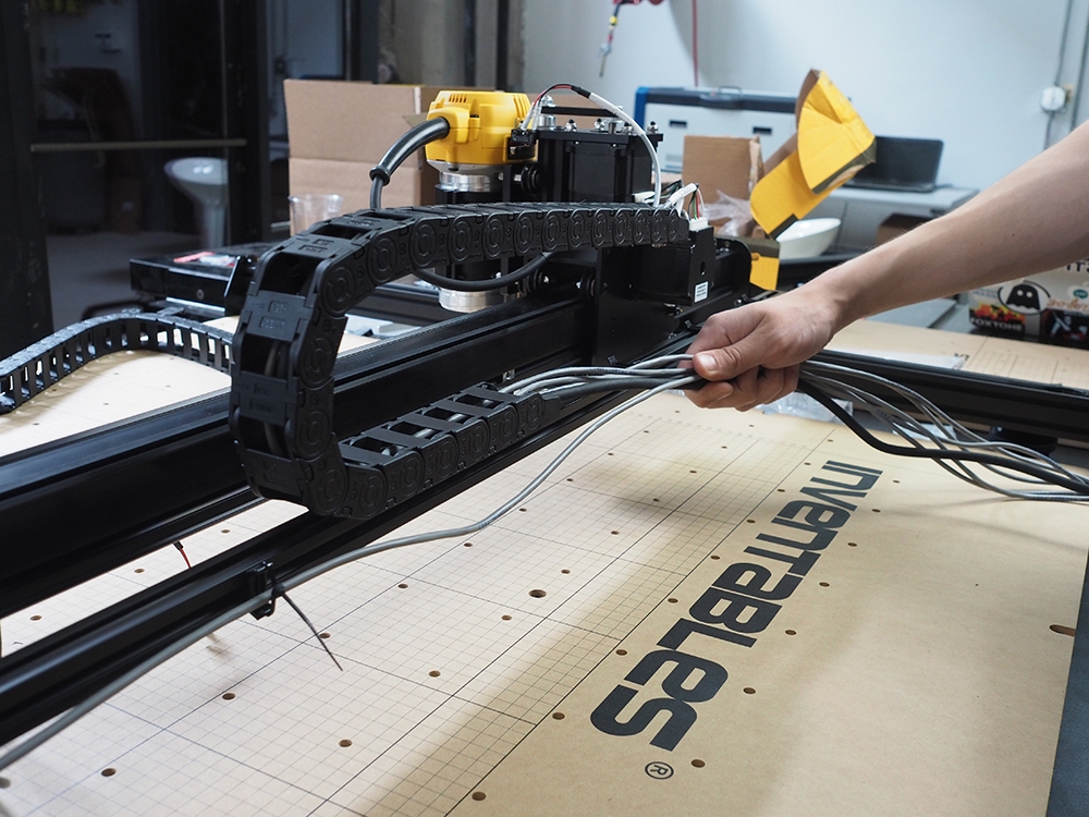
Place the Makita power cord, z-axis stepper motor wire (30679-12), x-axis stepper motor wire (30679-09), z-axis homing switch wire (30682-09), x-axis homing switch wire (30682-07), and z-probe wire into the drag chain. Take note of the wiring orientation.
Take note of the wiring orientation. Each wire will have a connector and an exposed wire end. The connectors should be placed together at the top of the drag chain and the exposed wire at the bottom of the drag chain. Close the drag chain hinges.
Once all drag chain hinges are closed, flip the drag chain around and attach the drag chain to the bracket that we installed into the extrusion behind the gantry. At this point, you can secure the end of the drag to the post-assembly tee nuts inside the extrusion by tightening fully.
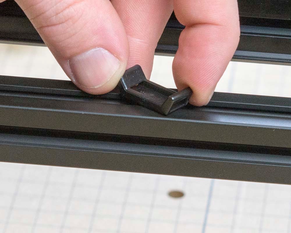
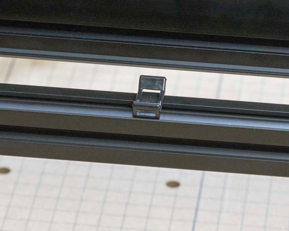
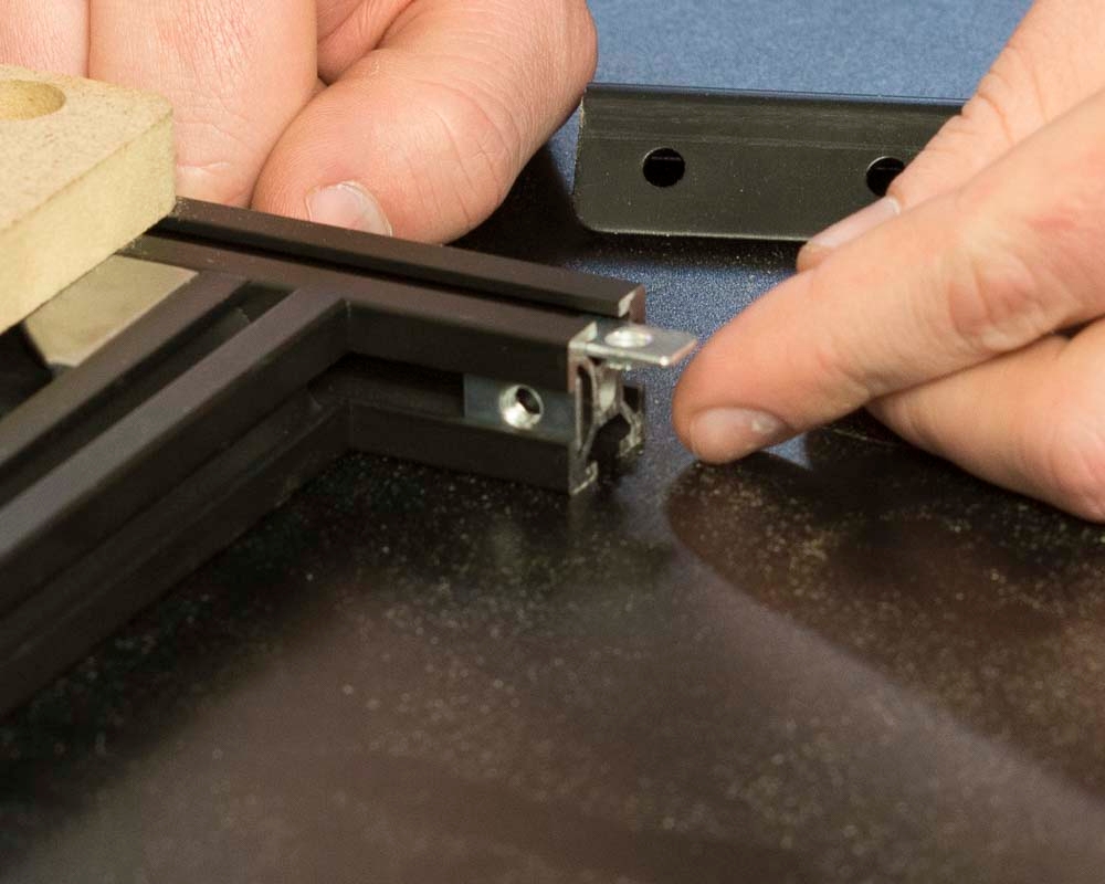
The zip tie mounts are placed with the tee nut shape in the extrusion and then twisted into place. You can also use the open end of the 10mm wrench from your toolkit to easily rotate them.
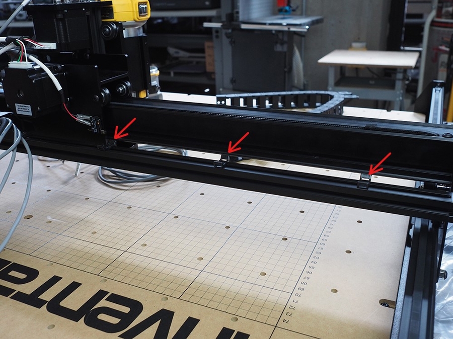
Place 2 zip tie mounts on the back side of the aluminum extrusion that the drag chain is resting on. Place 1 at the far end of the extrusion near the right-side Y rail, and the other about 12 inches toward the center of the machine. These zip tie mounts will hold the Y2 (right side) motor cable.
Plug in Y2 stepper motor cable (30679-11) and guide it across the rear of the aluminum extrusion and secure it to the zip tie mounts with zip ties.
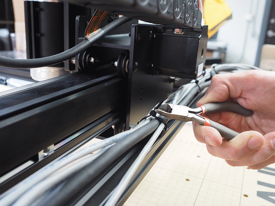
Gather up all the wires from the end of the top drag chain and the Y2 stepper motor. Zip tie them to the remaining 3 zip tie mounts.
Connect the Y1 axis motor cable and homing switch cable. Per the same process as above.
Using a small flat head screwdriver, open up the drag chain links just like in the previous step. Place M5x12mm flat head screws through the drag chain link and bracket, and e M5 nylon lock nuts. Use a 3mm hex key and 8mm wrench to tighten.
Ensure that the drag chain is correctly oriented, and that the open links are towards the outside of the machine.
Gather up all wires from the X axis drag chain and Y1 motor and homing switch cables.
Once all of the cables are placed in the drag chain, snap all of the drag chain links closed.
Wrap the drag chain under such that the cables are facing towards the front of the machine.
You can skip this step if you purchased the Sideboard kit.Lower Drag Chain Bracket (Optional- skip this if you have the Sideboard Kit)
Attach the drag chain bracket to the aluminum extrusion frame under the wasteboard using the M5x6mm button head cp screw and post-assembly insertion nut. This bracket can be installed in the gap between the acrylic stiffeners.
Install all threaded inserts into side board.
Insert 2 pre-assembly t-slot nuts on the side of each aluminum extrusion (facing inward). These will be used to attach the gusset brackets to the extrusions. Insert 1 additional pre-assembly t-slot nut on the top side of one of the 958mm extrusions to match up with the middle countersunk hole on the sideboard.
Loosely assemble frame using the 20mm x 20mm aluminum extrusion, 4 gusset brackets, 8 pre-assembly insertion nuts and 8 M5x10mm button head cap screws.
Place sideboard over the frame and line up 958mm extrusion with the pre-assembly t-slot nut under the middle countersunk hole. Tighten all 8 M5x10mm button head cap screws to secure gusset brackets. Slide 2 pre-assembly t-slot nuts on the top of the 250mm aluminum extrusions. Attach the sideboard to the frame by placing 5 M5x12mm button head cap screws in the countersunk holes and securing them into the pre-assembly insertion nuts.
Insert pre-assembly t-slot nuts into the ends of the sideboard and wasteboard frame. These will be used to attach the side board to the X-Carve frame using the extrusion connection brackets. Use M5 x 8 button head cap screws to secure the extrusion connection brackets.
Use 2 post-assembly t-slot nuts and 2 M5 x 10 flat head screws to secure the drag chain to the sideboard.
Lift the machine onto the side board and tighten down remaining button head cap screws.
NOTE: The M5 x 14 button head cap screws will be used to attach the X-Controller to the sideboard. Extra screws can be used to mount components not included with the X-Carve.
This section covers installing the belting.
Start by cutting the 4 meter length of belting into 3 equal sections. Each piece of belting should be just long enough to reach from corner to corner on the waste board, as shown below.
Each axis (X, Y1, and Y2) uses the same hardware and quantity. Lay out the belts and hardware listed above so each axis is ready for assembly. X-Carve Kits shipped after April 2022 will have a slightly different M5x25mm screw than what is shown below.
On the Y1 axis, route the belt (teeth side down) under the smooth idler, over the motor pulley, and under the other smooth idler. Lay the rest of the belt across the Y-axis such that there is a bit of overlap on each side. Repeat this for the Y2 axis.
Now you will install the belt on the X-axis.
The X-axis is by far the trickiest of the three. You won't be able to route the belt over the pulley by going in from the side of the x-carriage, so you'll need to go through the hole in the top. This works best if both ends are first curled before placing them through the top hole.
Feed one curled belt end between the pulley and smooth idler, and instead of forcing the belt through, slowly move the X-Carriage in the opposite direction to help reveal the end of the belt. Once revealed, grab the belt and pull it further through. Repeat this process with the other end of the belt, and center the belt such that there is overlap on each side of the X-axis.
Adjust the belt as needed so that each end reaches the ends of the Gantry (Wide Makerslide).
Each end of the belt has a belt sleeve and is secured to the machine by a belt clip. Take one end of the belt and add one of the belt sleeves, small end first (wide end pointing towards the nearest end of the belt, with the tapered end closer to the center of the belt).
There is a very small difference in the opening size for the ends of the belt sleeve. The small notch pictured below indicates the larger opening on the belt sleeve. For the following steps, we will be inserting the smaller end (no notch) onto the belt first.
Route the belt through the sleeve (as pictured below), into the clip, and through the remaining slot. Push the end of the belt through the wide end of the belt sleeve to lock the teeth in place. Try to leave at least 2 inches of excess belting on each end, to ensure that there is enough length available for the teeth to lock into each other. Repeat this process for each end of the belts on the Y-axes and the X-axis.
Once all three sections of belting have the clip and sleeve attached to both ends, locate your M5x25mm Low Profile Socket Head Screws (or standard for pre-April 2022 X-Carves). Each section of belting only requires one tensioning screw).
Screw Placement: When facing the machine (X-Carve label on gantry facing you, sideboard to the left of the machine), the Y-axes should have the M5x25mm tensioning screw towards the back, and the X-axis should have the tensioning screw towards the right-hand side of the Wide Makerslide
Insert the M5x25mm screw from the inside of the clip into the hole marked with the orange arrow below, so that the post of the screw sticks out from the clip and the head of the screw lies on the inside of the bend.
Next, place an M5x8mm button head cap screw through the belt clip into the remaining circular hole, on the same face as the belt loop. Placing both screws through the holes prior to threading them into their respective locations will make it easier to access the screw heads with a hex key.
Once the screws are inserted into the clip, thread the M5x8mm button head cap screw into one of the two pre-assembly t-slot nuts that were inserted into the X and Y-axes in a previous step. You may need to slide the t-slot nuts along the extrusion channel to the appropriate location. Then, place the M5x25mm Low Profile Socket Head Screw through the hole of the rear riser plate (Gantry Side Plate [Right] for X-axis tensioning screw), add an M5 washer, and hand thread an M5 nylon lock nut just enough so that it is secure.
Once the belt clips with tensioning screws have been secured to the rear sides of the Y-axes and the right side of the X-Axis, you will secure the other end of each belt.
Start with the unsecured end of the Y-axis belts. Remove as much slack from the belt as possible by pulling the excess through the belt clips and then hold the belt clip flush with the front end plate. Limiting the slack in the belt will make tensioning easier.
Place an M5x8mm button head screw through the belt clip (next to the belt loop, as shown below) and tighten it to the other pre-assembly t-slot nut we installed earlier. Secure the screw and nut loosely with a 3mm hex key.
Repeat this step on the remaining belt clips, securing them with an M5x8mm button head screw threaded into the M5 pre-assembly t-slot nut inserted into the extrusion channel, with the end of the belt clip flush with the end plate (or side plate, for the X-axis).
It is important to not waste any threads on your tensioning screw, since you will need to tighten the screw a bit to achieve the proper tension. The best way to do this is by starting with some* (*read: "as much as possible") tension in your belt. You should be able to pull the front belt clips flush to the end plates without the belt fighting you, but you really do not want any more belt-length between the clips than what is required. If you start with tension already in your belt, you won't have to deal with undoing the tensioning screw and feeding more belt through the belt clip; essentially redoing all of the work you just did.
To begin adjusting the tension of the belts, pull any excess length through the belt clips, the excess can be trimmed later. Then, place your hex key in the head of the M5x8mm button head cap screw on the front clip (without the tensioning screw) and pull towards the front of the machine making the belt tight. With the clip flush to the end/side plate, tighten the button head cap screw in place.
Once you achieve that tone (similar to a bass string on a guitar), tighten down the remaining M5x8mm button head cap screw on the rear (or right side, for the X-axis) belt clip to secure the assembly in place. Ensure that all three belts are secured tightly on both ends and that they are tensioned properly before carving.
Place the remaining 3 zip tie mounts on the top of the drag chain extrusion, evenly spaced from the end of the drag chain all the way to the Y1 (left side) motor.
If you’re having trouble with the X-axis belting, check out this Community Forum post:
Then, go back to the tensioning screws on the opposite end and start tightening down the M5 nylon locking nut until you have reached the appropriate tension. There are more specific tension-calibration tips in the section of the instructions. For now, though, we are looking for the belts to make an audible noise when plucked.
For more information on tensioning your belts or to check that your V-wheels are properly tensioned, you can use the .
1000mm Rail Kit
SKU
Name
Quantity
26049-02
Aluminum Extrusion 20mm × 20mm Black 1000mm Long
1
26018-01
Extrusion bracket (gusset)
2
M5 Tee Nut
6
M5x10mm Button Head Screw
4
SKU
Name
Quantity
M5 Tee Nut Twist On
4
26018-01
Extrusion bracket (gusset)
2
M5x10 Button Head Screw
4
4
SKU
Name
Quantity
25281-10
M5 Tee Nut
3
M5x12 Button Head Screw
5
M5 Flat Washer
10
MDF Back Board
1
SKU
Name
Quantity
5mm Hex Driver Bit
1
30517-18
Threaded Inserts
200
SKU
Name
Quantity
Extrusion Bracket (gusset)
2
M5x10mm Button Head Screw
4
M5 Tee Nut Twist On
4
Core Components Kit
SKU
Name
Qty
25286-38
Button Head Cap Screw M5 x 12
4
1000mm Drag Chain Kit
SKU
Name
Qty
26049-09
Extrusion T-Slot 20x20 x 1000mm Tapped
1
25286-46
Button Head Cap Screw M5 x 14
2
30681-01
Drag Chain Support Arm
2
1000mm Drag Chain Kit
SKU
Name
Qty
Drag chain
2
30554-06
M5x10mm Flat Head Screw
2
M5 Post-assembly Tee Nut
2
M5x12mm Flat Head Screw
2
30265-10
M5 Nyon Lock Nut
2
SKU
Name
Qty
30679-09
X Axis Motor Cable
1
30679-12
Z Axis Motor Cable
1
30682-07
X Axis Homing Switch Cable
1
30682-09
Z Axis Homing Switch Cable
1
30680-01
Zip Tie Mount
5
30679-11
Y2 Axis Motor Cable
1
30679-10
Y1 Axis Motor Cable
1
1000mm Drag Chain Kit
SKU
Name
Qty
Drag chain
1
M5x12mm Flat Head Screw
2
30265-10
M5 Nyon Lock Nut
2
1000mm Drag Chain Kit
SKU
Name
Qty
30527-06
Long Drag Chain Bracket
1
25286-31
M5x6mm Button Head Screw
1
26016-03
M5 post-assembly tee nut
1
1000mm Side Board Kit
SKU
Name
Quantity
30684-01
Extrusion Connection Bracket
2
25281-13
T-Slot Nut M5 Pre-Assembly
21
26018-03
Extrusion Bracket (Gusset)
4
30517-11
Threaded Insert M5
12
30685-03
Side Board, X-Carve 1000mm
1
26049-10
Extrusion T-Slot 20x20 x 250mm
2
26049-04
Extrusion T-Slot 20x20 x 958mm
2
25286-34
Button Head Cap Screw M5 x 8
8
25286-37
Button Head Cap Screw M5 x 10
8
25286-41
Button Head Cap Screw M5 x 12
5
25286-47
Button Head Cap Screw M5 x 14
12
1000mm Drag Chain Kit
SKU
Name
Quantity
30554-06
Flat Head Cap Screw M5 x 10
2
26016-03
T-Slot Nut M5 Post-Assembly
2
9mm Belt and Motor Kit
SKU
Name
Qty
26053-04
3GT Belting 9mm (4 meters)
1
30858-01
Belt Clip 9mm
6
30677-04
Belt Sleeve
6
Core Components Kit
SKU
Name
Qty
30900-01
M5x25mm Low Profile Socket Head Screw
3
25287-13
M5 Flat Washer
3
25286-33
M5x8mm Button Head Screw
6
30265-09
M5 Nylon Lock Nut
3
In this section we’ll be assembling the X-Carriage. This carriage carries the components for moving the X axis as well as the Z axis.
Core Components Kit
SKU
Name
Quantity
30545-01
X Carriage Extrusion
1
30552-05
Flat Head Screw M5 x 35
2
25312-23
Aluminum Spacer 5.1mm ID 9.5mm OD 9.5mm LG
2
30265-09
Nylon Insert Lock Nut M5
2
9mm Belt and Motor Kit
SKU
Name
Quantity
25197-10
Smooth Idler Pulley Assembly
2
25287-12
M5 Flat Washer
4
Insert an M5x35 flat head screw into one of the countersunk holes in the X-Carriage.
Put an aluminum spacer on the screw followed by an idler wheel, two M5 flat washers and a nylon locking nut. Make sure that the side of the wheel with the recessed bearing faces away from the aluminum spacer (the washers and nylon lock nut will sit inside the pulley), similar to the Y axis plates. Use a 3mm hex key and 8mm wrench to tighten the assembly.
Be sure to include (2) washers before installing the nut.
Repeat this process for the other countersunk hole. Your carriage should now look like this:
Core Components Kit
SKU
Name
Quantity
25286-43
Button Head Cap Screw M5 x 25
4
25287-12
M5 Flat Washer
4
25203-01
V Wheel Assembly
4
30265-09
Nylon Insert Lock Nut M5
4
This process is similar to attaching the fixed V-Wheels on the gantry side plates.
Place an M5x25mm button head cap screw through the hole the opposite side of the idler pulleys we just installed, per the image below.
Next, add an M5 washer onto the screw inside of the carriage.
Finally, place the v wheel and M5 nylon lock nut on the screw. Tighten with a 3mm hex key and 8mm wrench.
Repeat this process for the other 3 holes on the lower side of the X carriage. Note that on this side of the X carriage there are 2 flanges outside of the rectangular frame, whereas the opposite side has 1. Ensure that the v-wheels are all inside of the carriage and that they are snug. When complete, your X carriage should look like the below picture.
Core Components Kit
SKU
Name
Quantity
25286-49
Button Head Cap Screw M5 x 30
4
25195-07
Short Eccentric Spacer
4
25287-12
M5 Flat Washer
4
25203-01
V Wheel Assembly
4
30265-09
Nylon Insert Lock Nut M5
4
Begin by placing a short eccentric spacer (25195-07) on an M5x30mm screw, then place the screw and spacer through one of the 4 remaining holes on the X carriage for the adjustable v-wheel. Make sure that the circular part of the spacer is facing the carriage and fits into the hole on the plate.
Place an M5 Flat Washer on the screw inside the carriage.
Then, place a v-wheel onto the screw.
Finally, add the M5 nylon lock nut on the end of the screw, then tighten with a 3mm hex key and 8mm wrench.
Repeat this process for the remaining v-wheels. When complete, your carriage should look like this:
Core Components Kit
SKU
Name
Quantity
25285-54
Socket Head Screw M5 x 10
4
9mm Belt and Motor Kit
SKU
Name
Quantity
25311-10
Stepper Motor - NEMA 23
1
Place the motor on the X-Carriage with the white connector facing the end of the X carriage that has 2 flanges, per the image below. Use a 4mm hex key to secure the motor in place using the threaded holes on the carriage. Note: there may be a small gap between the motor and the carriage due to the heads of the M5x35mm flat head screws that hold the smooth idlers. Tighten the screws in an alternating pattern to ensure that they are evenly secured.
1000mm Drag Chain Kit
30527-05
Drag Chain Bracket
1
25286-44
Button Head Cap Screw M4 x 10
2
Insert 2x M4x10mm button head screws through the drag chain bracket into the X carriage in the tapped holes beside the motor we just installed. Use a 2.5mm hex key and tighten the bracket to the X carriage, where the bottom of the bracket is flush with the X carriage flange as pictured below. You will install the drag chain later on.
We recommend reviewing all the steps before logging in to Easel or opening the Machine Setup page in a separate tab.
To start, power on your X-Controller. You should see the LED lights, on the front and back, light up as well as the rear fan spinning. Make sure the e-stop button is disengaged. If the e-stop is engaged, the X-Controller will not power on or connect to Easel.
If you already have an account, you can log into your account. Otherwise, enter your email address and create a password for a new account.
If you are already logged in to Easel, click on "Machine" and "Set up new machine" to get started.
If you're not logged in to Easel, use the link below:
Once you're logged in and in the Machine Setup, choose your machine type. After selecting your machine, you'll need to connect it to Easel.
If you need help installing drivers, follow these guides:
Once your X-Controller is connected to your computer, click "Continue with setup."
If the machine successfully connects, you'll be presented with a set of controls for jogging your machine.
Try jogging the machine using the directional arrows.
When standing in front of the X-Carve, X should jog the carriage left to right. Y should jog the gantry away from you and towards you. Z should jog the spindle up and down.
If everything is moving correctly, select Yes. If one is reversed, you can either go back and re-wire your motors or let Easel change the direction in the firmware settings by clicking No in the menu.
Click continue when all axes are moving correctly. You'll now be prompted to enable or disable homing.
If you enable homing, you'll be prompted to start the homing sequence.
The homing sequence will move the z-axis to the top until the homing switch is actuated. The X-Carve will then move towards the front-left corner until the x and y axis homing switches are actuated. A successful homing sequence will take you to the last step.
The last step is enabling up the z-probe. You can also skip this step and enable the z-probe later. The image above shows how the z-probe should be connected to the X-Carve. You do not need to have a bit installed during this step.
If you want to continue with the setup, select Yes to test the continuity of the z-probe.
Follow the steps on the screen. Make sure to click "Clip is attached" button, otherwise, the setup may not allow you to continue.
Once your z-probe makes contact, you can continue and finish the setup.
After setting your machine, you can run a test carve to ensure that the machine is operating properly. Clicking on the green button here will take you to the test carve project itself. Follow the steps in Easel to complete your first carve!
You can use any material you'd like for this initial carve, though we generally recommend working with wood or soft plastic to begin with.
Note: If you are setting up a machine purchased before November 2021, you'll need to go through the Advanced Menu and ensure you select the correct hardware. If you choose the incorrect settings, your machine will not move accurately.
Click on one of the buttons below to get started with Easel.
In this step we will install the risers that create a rigid connection between the Y-Axis rails and the machine base.
Core Components Kit
SKU
Name
Quantity
25281-12
M5 Tee Nut Pre-Assembly
4
Z-Axis / Riser / Stiffener Kit
SKU
Name
Quantity
30844-01
Riser Plates
4
30874-01
Riser Upgrade Hardware Subassembly
Socket Head Screw M5 x 14
8
Socket Head Screw M5 x 10
8
M5 Tee Nut Twist On
8
Insert 2x M5 pre-assembly t-slot nuts into the top slot of each Y axis makerslide rail. These will be used to hold the belts in a later step.
Begin by placing 2 M5x10mm socket head screws through the bottom holes on the riser plate and loosely thread an M5 Tee Nut onto each.
Place the riser against the corresponding Y axis and then thread 2 M5x14mm socket head screws through the second and third holes from the top per the image below.
Using a 4mm hex key, tighten all 4 screws on each riser. Repeat this process for the remaining 3 risers and ensure that the orientation of the riser plate aligns with the edge of the stiffeners.
Core Kit
SKU
Name
Qty
25286-38
Button Head Cap Screw M5 x 12
4
25287-12
M5 Flat Washer
2
25281-XX
T-Slot Nut M5 Pre-Assembly (28058 - Tee Nut - M5 - Qty 4)
2
Rail Kit
SKU
Name
Qty
30678-03
Wide MakerSlide, 1000mm
1
We will now assemble the main gantry of the machine using the sub-assemblies you’ve built thus far. After this is assembled, your machine’s frame will almost be complete.
Start by inserting 2 M5 Tee Nuts into the groove on the top side of the wide MakerSlide rail. These will be used to secure your belts. Note that the Tee Nuts are placed in the extrusion on top of where the X-Carve lettering is per the below image.
Slide the completed X-carriage onto the Makerslide rail. The stepper motor should face away from the X-Carve logo on the front of the wide Makerslide, and the X-carriage should be oriented such that the side with 2 flanges is on the top.
If the x-carriage does not slide on smoothly, you may need to adjust the v-wheels with the eccentric spacers. The eccentric spacers have a small impression on one side that will help to determine the proximity of the v-wheel. With the impression facing in the opposite direction of the extrusion (see below image), there will be more space for the extrusion to slide through on the v-wheels.
Now we will be attaching the gantry to the Y plates we completed in earlier steps. If the Y plates do not smoothly onto the Makerslides, adjust the v-wheels per the same process as above.
Slide the assembled Y plates onto each Y axis Makerslide to ensure they fit smoothly for when we install the gantry. If the Y plates do not smoothly onto the Makerslides, adjust the v-wheels per the same process as above. Remove the Y axis plates from the Y Makerslides.
Attach each of the Y plates loosely to the X axis wide Makerslide using 2 M5x12mm screws. You will use a single M5 washer per side on the exposed slotted hole in the plate. You can use one of the empty X-Carve boxes to hold up the gantry while you install the Y plates.
Make sure the angled side of the plates and the X-Carve logo on the gantry rail are facing in the same direction.
You will now slide the gantry assembly onto the machine frame. The X-Carve logo should face the front of the machine. Once you have installed the gantry onto the machine, use a 3mm hex key and tighten the 4x M5x12mm screws that secure the Y plates to the wide Makerslide.
Z Axis Kit
SKU
Name
Qty
30749-01
Z Probe Relocation Bracket
1
30756-01
Z Probe Relocation Hardware Kit
1
M5 Flat Washer
1
M5 Nylon Lock Nut
1
M5x12 Flat Head Screw
1
Router Mount
SKU
Name
Qty
30839-01
Makita Router Mount
1
30831-01
Router Mount Hardware Kit
1
Gather the hardware from the Z-Probe Relocation Hardware Kit.
Place the M5x12 flat head screw through the bored hole on the top right side of the X carriage. Place the bracket behind it followed by the flat washer and nylon lock nut per the image below.
Tighten the bracket using a 4mm hex key and 8mm wrench.
Z Axis Kit
SKU
Name
Qty
30677-04
Z Axis Assembly
1
30871-01
Z Axis Hardware Kit
1
M5x10 Button Head Screw
4
M5 Tee Nut
M5X16 Socket Head Screw
M5 Flat Washer
30752-02
Dust Shoe Alignment Labels
2
30837-05
Clear Inventables Sticker
1
Place a dust shoe alignment label on each side of the Z axis, lining up the bottom of the sticker to the bottom of the extrusion.
Repeat with the other sticker on the other side. The Inventables logo will be at the bottom of the extrusion.
Gather 4 M5 Tee Nuts and 4 M5x10mm button head screws.
Place an M5x10mm button head screw through each hole in the front of the X carriage and thread on a Tee nut. Be sure that the Tee Nuts are facing the front of the machine and oriented as shown in the below picture. Note, your kit may have 4 M5 Twist On Tee Nuts instead of the pre-assembly Tee Nuts as pictured below. Both versions will work for this application.
There are 2 extrusion channels on the back of the Z axis assembly. From the top down, slide the Z axis through all 4 of the Tee Nuts we just installed.
While holding the Z axis with one hand, tighten all 4 M5x10 screws using a 3mm hex key.
There is a plate on the bottom that prevents the router mount from riding down off the rail. If you're using a short bit, the router may be hitting that bottom plate before the bit can reach the table.
Using a short bit, such as a v-bit, lower the router so it is at the lowest position. If the bit does not reach the wasteboard, loosen the 4 screws holding the z-axis assembly, lower the z-axis and ensure the z-axis is square before tightening.
Be careful when lowering the z-axis with a bit installed. The z-axis is heavy and will drop if not supported as you loosen the screws.
SKU
Name
Qty
M5X16 Socket Head Screw
4
M5 Flat Washer
4
Makita Spindle Mount Kit
30839-01
Makita Router Mount
1
30831-01
Router Mount Hardware Kit
1
M5x16 Button Head Screw
2
M4x16 Socket Head Screw
3
Place an M5 flat washer through each M5x16mm socket head screw. Secure the router mount to the Z-axis assembly using the M5x16 screws with washers and tighten with a 4mm hex key. Note, the router mount should have the holes to secure the Makita router on the right-hand side.
In this step you’ll be mounting the included router into the spindle mount. Begin by removing existing base from the spindle. This will leave just the metal router body.
Use a screwdriver or other prying tool to gently pry the spindle mount open and fully insert the router.
Thread the 3 M4x16 socket head screws through the holes on the router mount. Using a 2.5mm hex key, tighten the 3 screws a little at a time, moving between the screws until all 3 are snug.
The router power cable will be put in the drag chains alongside the stepper motor cables in the next step. The router is powered with a simple AC wall outlet.
Your router will include tools for changing the bit. Set these aside, as you will need them when you start carving.
Welcome to the X-Controller assembly instructions! The images shown at the beginning of each step show the finished results of that step. This provides context for what you're about to start working on, and offer those eager and willing to figure things out on their own a way to skim through more quickly. Click on the thumbnails to see more details.
Each step also begins with a bill of materials (BOM) that details the necessary components to complete the step. Please review the full bill of materials, listed below, before getting started. Few things are more frustrating than being partway through a build and suddenly discovering something is missing.
Click the black bar below to reveal the BOM and make sure you received everything. Note that the FRONT AND BACK PANELS are located in the styrofoam inserts. If any parts are missing, please contact us at help @ inventables.com for replacements.
SKU
Name
Quantity
01
Chassis
1
02
Enclosed Power Supply
1
03
Power Supply Interface PCB
1
04
Power Supply Phillips Head Screws (attached to power supply)
5
05
Main Controller PCB
1
06
Ribbon Cable
2
07
E-Stop Cable
1
08
E-Stop Button
1
09
Top Panel
1
10
Buttons PCB
1
11
Nylon Threaded Standoff M3
4
12
Button Head Cap Screw M3 x 6mm
4
13
USB Bulkhead Cable
1
14
Front Panel
1
15
Socket Head Cap Screw M4 x 8mm
8
16
Back Panel
1
17
Nylon Hex Nut M3
4
18
Terminal Block 4C 5mm Plug
4
19
Terminal Block 8C 3.5mm Plug
1
20
Terminal Block 7C 3.5mm Plug
1
21
USB Cable
1
22
Power Cord
1
Tools
Phillips Screwdriver
2.5mm Allen Wrench
3mm Allen Wrench
5.5mm Open End Wrench (Adjustable Wrench or Pliers)
SKU
Name
Quantity
02
Enclosed Power Supply
1
03
Power Supply Interface PCB
1
04
Power Supply Phillips Head Screws
5
Unscrew the Phillips head screw from the power supply. Attach the power supply interface PCB using the power supply Phillips Head screws.
Using the M4 x 8mm button head cap screws, attach the power supply through the mounting holes on the underside of the chassis. The threaded holes on the base of the power supply are delicate, so try not to overtighten the screws when assembling. The two remaining M4 x 8mm button head cap screws can be installed in the threaded holes on the sides of the chassis.
Note: The chassis is not symmetrical. The power supply interface PCB will be flush with the end of the chassis when installed correctly.
SKU
Name
Quantity
06
Main Controller PCB
1
08
Ribbon Cable
1
09
E-Stop Cable
1
Attach the ribbon cables and the e-stop connectors to the power supply interface PCB. The cables can only be connected in one orientation. Make sure the ribbon clamps are in the open position. If the cables don't attach well, double-check them and try again. Try orienting the cables so that the wires easily travel from board to board.
Note: Make sure to tuck the e-stop cable along the edge of the enclosed power supply to prevent snagging or pinching.
For your X-Controller to work correctly with your X-Carve, you must check the current potentiometers and microstepping switches for each axis. You shouldn't need to make any adjustments, just confirm your board looks like the configuration shown below:
Slide the controller board into the channels of the chassis, making sure you route the wires through the cutout on the board to prevent snagging or pinching. The two remaining M4 x 8mm button head cap screws can be installed in the threaded holes on the sides of the chassis. The screws act as stoppers, preventing the controller board from moving around within the chassis.
Note: The wires might be stiff. If you're having trouble, don't force the wires. Try shaping the wire into place. Double-check all of your connections before moving forward, in case the wires snag and become loose when sliding into position. If your main controller board does not slide in, pull the chassis sides open.
Connect the ribbon cable and e-stop button cable from the power supply interface PCB to the main controller PCB as shown below:
SKU
Name
Quantity
08
Ribbon Cable
1
10
E-Stop Button
1
11
Top Panel
1
12
Buttons PCB
1
13
Threaded Standoff M3
4
13
Nylon Hex Nuts M3
4
14
Button Head Cap Screw M3 x 6mm
4
15
USB Bulkhead Cable
1
16
Front Panel
1
17
Socket Head Cap Screw M4 x 6mm
4
Remove the button from the screw terminals by gently pulling on the yellow tab. With the button upside down (as pictured), pull the tab towards you and then to the right to disengage the two parts. Unscrew the black nut attached to the base of the button. This nut will be used to secure the button to the top cover.
Insert the button through the hole on the top panel and secure using the nut.
Make sure the side of the button marked "TOP" is facing the center of the top panel. Set aside.
Note: When wiring the e-stop in subsequent steps, make sure the "TOP" marking on the button lines up with the "TOP" marking on the screw terminals.
First, install the nylon threaded standoffs to the buttons PCB board. Insert the male end of the standoff through the buttons PCB from the front, securing each standoff in the back using a nylon hex nut on the back side. The standoff should be on the front side of the board to act as a spacer between the board and front cover (see 2nd image below).
Align the buttons PCB with the button holes in the front panel and attach the PCB with the M3 x 6mm button head screws. Next, secure the standoffs to each corner of the board.
Then, remove the silver Phillips head screws from the USB cable terminal. Attach the USB cable terminal to the front panel from the backside of the panel. Secure it in place using the Phillips head screws.
Don't attach the front panel to the chassis until the rest of the e-stop is installed in the next step.
Loosen the Phillips head screws on the e-stop screw terminals and attach one end of the e-stop cable to each side of the NC screw terminal. Both cables are red; it does not matter which cable goes into which side. Tighten the screws on the screw terminals to hold the cable in place.
Next, connect the remaining ribbon cable to the main controller board, and the other end on the back of the buttons PCB board on the front panel. Additionally, attach the other end of the USB cable to the main controller board.
Slide the top panel into the channels of the chassis. Attach the Emergency Stop wired screw terminal to the button, line up the "TOP" marking on the button with the "TOP" marking on the screw terminal. Once in position, move the yellow tab towards the back of the assembly to lock in place.
Attach the front panel using the included M4 socket head cap screws.
Note: If you're having any problems with this part of the assembly, please reach out to help@inventables.com or call 312-775-7009.
SKU
Name
Quantity
17
Socket Head Cap Screw M4 x 6mm
4
18
Back Panel
1
19
Flat Washer #4/M3
4
20
Fan
1
21
Socket Head Cap Screw M3 x 20mm
4
22
Hex Nut M3
4
Using the included M3 socket head cap screws, nuts, and finger guard, attach the fan to the front panel with the wires pointed down. Make sure the fan label faces the inside of the X-Controller.
Attach the fan cable to the power supply interface PCB. The cable can only be connected in one orientation. If it doesn't attach well, double-check it and try again. Ensure the ribbon cable connector at the power supply interface PCB and attach the back panel using the included M4 x6mm socket head cap screws. You may need to wiggle the lower PCB in place when installing it, in order for the back panel to align flush with the chassis.
Wire the cables into the green terminal block plugs by inserting the exposed metal ends of each wire and tightening the screws until the wire is held firmly in place. Plug the block plugs into the corresponding spots on the X-Controller. The screws on the terminal blocks will face upward, and you should feel the blocks click into place. Make sure the colors on the wires match the colors in the diagrams.
With two motors on the y axis facing each other, you'll need to flip one of the Y-Axis pairs for the motors to move in the same direction. The diagram above shows the black and green wires flipped on Y2 AXIS.
Note: The stepper motors will act as generators when moved manually and will feed current back into the X-Controller, potentially damaging the stepper drivers and other components. If you want to move the gantry manually, make sure the stepper motor cables are disconnected from the X-Controller.
Wire the homing switches to their respective terminals on the X-Controller. Make sure that the red wire is connected to the limit switch pin and the black wire is connected to the 'GND' pin on the connector.
Note: NEVER hook a spindle directly up to the X-Controller. These are only control signals, NOT power.
If you have a Z-Probe on your machine, wire the red wire into the 'Probe' Port on the same terminal block as the limit switches and the black wire to the adjacent 'GND' connection.
The remaining terminal block plug is used for more advanced spindle options, such as a relay or VFD controlled spindle, and will not be used in a stock X-Carve configuration.
Use the M5 x 14 button head cap screws from the Sideboard Kit to attach the X-Controller to the sideboard. If you do not want to mount the X-Controller to the sideboard, use the rubber feet.
The X-Controller Has 4 buttons on it. The red button is the e-stop (emergency-stop) which cuts the power to the machine. Press down on it to activate it and twist it clockwise while pulling up to deactivate it. Do not use it as a regular off switch.
The grey buttons on the front of the X-Controller are used during carving. The first button pauses the carve and raises the bit. The second resumes the carve. The last button stops the carve and cancels the project.
Check to make sure your e-stop button is pulled out and not engaged.
Check that the ribbon connectors are fully pushed into the mating connectors.
Squaring your rails is essential for your X-Carve to move correctly and carve smoothly.
If you see ridges in your carves, ensure the bit is perpendicular to the wasteboard by squaring the z-axis. Put the machine on a flat surface and use a large square ruler to see if the Z-Axis is square to the table (as pictured above). If it is not squared, locate the four button head cap screws that are behind the x-carriage. These button head cap screws hold the Z-Axis Makerslide in place (2 on the top and 2 on the bottom). Loosen the button head cap screws and adjust the Z-Axis until it is square to the table. Once it is squared, retighten the screws and square it one more time to make sure.
You may also notice carves are deeper on one side than the other. This could be due to the wide Makerslide being tilted forward on the left or right side.
Use a large square against the rail and on top of the wasteboard. There should be no gap between the square and the wide makerslide (as pictured above). If you see a gap, loosen the 4 button head cap screw at the end plate of the wide makerslide, turn the makerslide, and tighten the four screws back up. Repeat on the opposite side as needed. If your carves are still deeper on one side than the other, check the squaring of the Y-axis rails.
To ensure your machine is moving correctly, you need to make sure the Y1 and Y2 rails are parallel from front to back. You can do this by measuring the diagonals between the end plates (left back to front right, then front left to back right). If those measurements aren't the same, you can adjust the rails by loosening up the screws holding the end plates to the waste board, allowing you to move the rail. You may also need to loosen the M5x8 Button Head cap screws on the stiffener panels to avoid damaging the panels when shifting the rails.
As you tighten the screws, push down on the rails to ensure the rails are tightened at the same height.
If you notice your carves are offset or your X-Carve does not say on path, you may need to adjust the belt tension. Start by jogging the gantry/carriage all the way to one side. Once it is in position, make sure the X-Controller is powered off so there is no resistance on the motors.
For the x and y-axis belts, pull from the center of the belt up an inch and you should feel some resistance. It shouldn't be impossible to pull it up an inch, nor should it feel slack. You can adjust the tension by feeding more or less of the belt through the clip or tightening the tensioning screw.
First, locate the belt clips without the tensioning screw. Ensure these clips are sitting straight and parallel with the makerslide and also make sure it is sitting flush with the end plates.
Next, locate the belt clip with the tension screw and loosen M5 x 8mm screw that attaches the belt clip to the makerslide. Using an allen key and wrench, tighten the M5 nut on the tensioning screw a couple of turns to desired belt tension. Once the belt is tensioned, tighten the M5 x 8mm screw to secure the belt clip to the makerslide.
Do not over tension as this can cause the stepper motor pulley or belts to snap.
Repeat these steps on the other belts.
If your machine is skipping steps or losing position, your eccentric v-wheels may not be properly positioned.
The first step is to locate the adjustable v-wheels. On the X-Carve, the v-wheels are categorized as either fixed or adjustable. The fixed v-wheels are attached by a regular nylock nut while the adjustable v-wheels are attached by an eccentric spacer. This video demonstrates how the adjustable v-wheels work:
Note that every fixed v-wheel has an adjustable v-wheel associated with it.
There are 8 v-wheels on the X-Carriage, 4 on each Y-Axis plates. After you’ve located the v-wheels, tighten the fixed v-wheels on the machine then adjust the corresponding adjustable v-wheel.
To properly position the adjustable v-wheel, take an open-ended wrench and slowly turn the eccentric spacer to the point where it takes a little bit of effort for it to spin. Do this slowly to ensure you do not over-tighten the v-wheel. This can cause the wheels to crack. Now repeat this step for every pair of v-wheels. Finally, test the wheels by moving the carriage using the Jog Controls in Easel. If the wheels moves along with the carriage without much effort, then they are properly tensioned.
Use a soft cloth to wipe down the v-groove on the rails. To clean the v-wheels, use a soft brush such as an old toothbrush to clear debris. Compressed air can also be used.
The brushes on your router do wear out with use. Changing the brushes takes a few minutes and we do sell replacements on our website. Follow the steps in this video for:
Makita Router Brushes
The replacement Instructions can be found in the Use and Warranty instructions that came with the Makita router.
In this step, you will be setting up your machine with the Easel. You'll want to make sure that your computer meets the System Requirements found .
All new Easel Pro accounts automatically start with a 30-day Easel Pro free trial. If you purchased Easel Pro as an add-on, make sure to Your Easel Pro Key can be found on your receipt. This will take effect once the trial expires.
For details on Easel Pro subscription, see the in our Support Center.
Easel is a web application and needs a small piece of software to allow it to talk to the USB port on your computer. The Easel Driver behaves like a printer driver in that you never have to open it to use Easel. You may have to update the Easel Driver from time to time, but you can generally install it and forget that it's there. If it doesn't open during the setup, you can access the
NOTE: If you're having trouble connecting your X-Controller on a computer running Windows, you may need to install the FTDI driver then restart your computer. for a direct download. The linked file is a .zip file, you'll need to extract the file.
Note: If your Y-axis is struggling to move, make sure that each motor is wired correctly. The Y motors should be wired to move in the opposite direction from one another since they are mirrored on the machine. You can refer to the diagrams in the assembly if necessary.
If you have any trouble connecting your X-Carve to Easel, check out our Support center .
Only enable homing if you have. If you have your home switches installed but don't want to test them now, you can always click No, disable homing and run your machine through this setup again.
If you have any trouble connecting your X-Carve to Easel, check out our Support center
You can use this point to check that your Y-Axes are square and level using the . You will need to loosen the stiffener panels to avoid damaging them when shifting the rails.
At this point, you can square the X-Axis using the .
After tightening the spindle into the spindle mount, you can square the Z-Axis using the .
Many of the mechanical problems you'll face can be fixed using the following information. X-Carve consumable components include:
You can find replacement parts in our
Optional: You can also check belt tension with a tension scale. We recommend 3lbs per inch displacement. For additional information on properly tensioning your belts, please check out this Community Forum thread:
The wasteboard is made out of MDF and this material can warp with changing environmental conditions and after use as the pressure from the router carving down will press down on the material. It is meant to be cut into to make sure you get full through-cuts. We recommend surfacing the wasteboard so it is flat in relation to the router's cutting path. This is a known best practice when CNC milling. Planing the wasteboard is recommended after ensuring the X-Carve is squared and tuned. In Easel, you can set up a square the size of the work area to approximately .01" depth. Before carving, home the X-Carve and use the Z-Probe for the best results. We recommend using a surfacing bit like the one in our . If you're concerned about alignment without a grid, try carving out your own grid after you have surfaced it. This is beneficial as you can make a grid custom to your needs. Some users opt for putting an additional sheet of MDF on top of their wasteboard and underneath their material. If you wanted to go this route, you would need to surface the "sacrificial" wasteboard to ensure it is flat and perpendicular to the spindle.

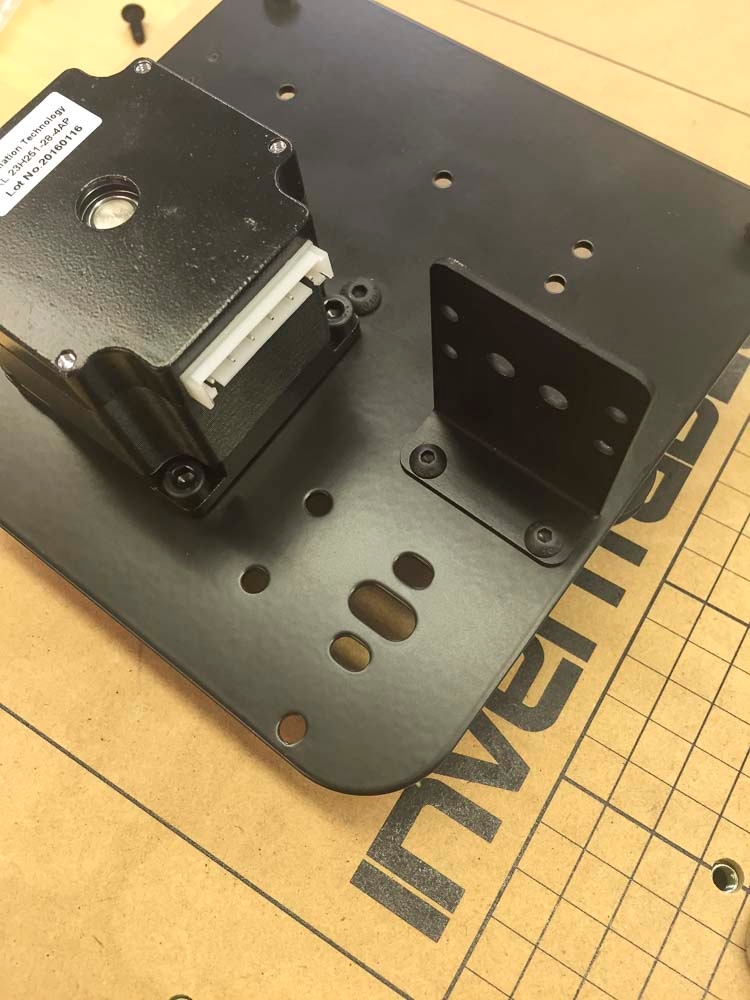
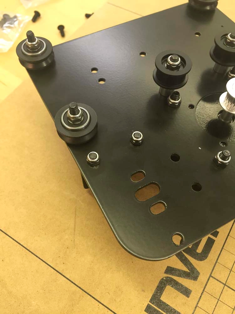
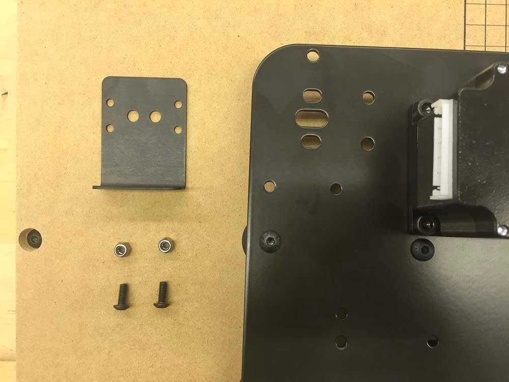
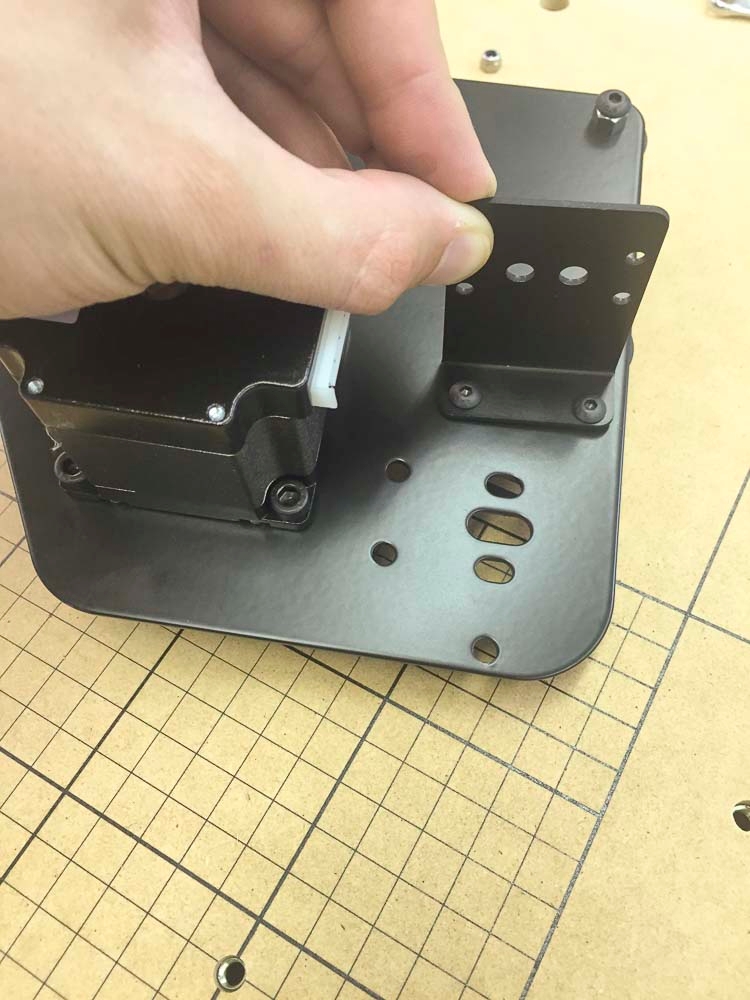
4mm Hex Key
3mm Hex Key
2mm Hex Key
8mm Wrench
10mm Wrench
In your box, you will find a number of larger parts as well as a smaller box of hardware. You’ll want to look for the following:
Conductive Hose
This connects the dust shoe to the vacuum. It is conductive and will dissipate static buildup when properly grounded.
Hose Support Poles
These poles fit together to suspend the hose assembly over the machine. The straight pole is the bottom pole and the pole with the two 45º bends fits on top.
Pole Support Bracket
This bracket mounts onto the right-front makerslide end plate on your machine and holds the bottom pole in place
Hose Clips
These mount on the hose support poles to hold the hose in place. Three mount on the top pole and two mount on the bottom pole. The threaded hole in each clip accepts a M5x8mm socket head cap screw to hold it in place. These screws are located in the Support Assembly Hardware Kit.
Support Assembly Kit
This hardware kit includes the necessary components to attach the pole support and the hose clips. It includes:
M5x8mm Socket Head Cap Screws (5x)
M5x12mm Button Head Cap Screw (1x)
M5x16mm Button Head Cap Screw (1x)
Grounding Kit
To prevent build-up of static during dust collection, your kit includes a grounding strap and the hardware to install it. This fits around the included hose which is conductive. This bag should include:
Hose Static Strap (1x)
Ground Wire Cable Assembly (1x)
Stainless Steel M5 Lock Washer (1x)
M5 Nylon Locking Nut (1x)
M5x12mm Stainless Steel Socket Head Cap Screw (1x)
Dust Shoe and Hose adapter
These attach to either end of the hose. The hose fitting on the dust shoe is glued onto the clear plastic body and is not removable. The hose adapter (right) press-fits onto the vacuum side of the hose.
Dust Shoe Support Arms
These support arms hold the dust shoe in place when in use. The channels with embedded magnets serve to lock the dust shoe in place.
Spindle Insert Plate
These replaceable inserts fit into the dust shoe to improve the vacuum seal of the assembly. They are pictured here with their removable plastic backing. We have included a spare insert in your kit, though only one is necessary for assembly.
Dust Shoe Hardware Kit
This kit includes the hardware necessary to attach the dust shoe supports to your machine. It should include the following hardware:
M5x8mm Button Head Cap Screws (4x)
M3x8mm Button Head Cap Screws (4x)
T-Slot Nuts (4x)
Clamp Thumb Screws (2x)
Locate the two dust shoe arms as well as the clamp screws that go with them. Note that these are mirrored parts and not interchangeable with one another. Note the small magnets on the bottom slot of each arm. These align with the magnets in the dust shoe and help to keep it in place.
Thread in the clamp screws into each arm. Thread them far enough in that the end of the screw almost comes through the other side of the threaded hole. This will make them easier to install.
Slide both arms into the slots on the brackets. Make sure that the channels in each arm are facing each other.
Secure each arm with the included clamping screw until snug
For your dust shoe to operate properly, you will need to install a small plastic insert on the underside to maintain the proper suction during cutting. This is designed to be replaceable so that damage from the bit, collisions, etc. is relatively limited. Begin by peeling the protective backing off of each side of the insert.
Now remove the protective film from the dust shoe itself.
Using four M3x8mm button head cap screws and a 2mm hex key, secure the insert to the shoe. The holes for the screws are already drilled and tapped. Take care to avoid cross-threading or stripping the holes.
Adjust the arm height as necessary then slide the dust shoe onto the slots in the two support arms. If the dust shoe doesn’t slide in easily, try loosening one of the arms slightly then tightening it when once the dust shoe is inserted. You’ll attach the hose to the fitting in a later step.
To suspend the vacuum hose, you’ll need to install the support pole on the lower right corner of the machine. Begin by locating the pole mounting bracket, along with two M5 x 14mm socket head screws and one M5 Nylock Nut from the Z Axis Upgrade Kit.
Use a 4mm hex key to remove the bottom right screw on the lower-right makerslide end plate.
Align the bracket with the holes on the makerslide end plate.
Secure the bottom part of the bracket with an M5x14mm socket head screw. You may have to re-align the t-slot nut for the bottom screw.
Secure the top part of the bracket with another M5x14mm socket head screw, this time with an M5 nylock nut on the back.
Now you can set up the support pole itself. First, Locate the two poles that make up the support arm.
Locate the five hooks that mount onto the poles and the five M5x8mm socket head cap screws that hold them in place. The screws thread into the hole on each hook to secure the hooks to the poles.
Install one hook onto the straight section of the pole as shown below. Use a 4mm hex key to secure the hook in the middle of the pole section.
Locate the angled pole and the four remaining hooks. Arrange the hooks as shown.
Insert the straight section of the pole into the bracket so that the tapered section is pointing up. The pole should be free to turn in the bracket so that it can swing back and forth during use. Install the bent pole on top of the straight section as shown.
Attach the dust shoe to one end of the hose, and the hose adapter to the other. The dust shoe fitting has a left-hand thread, so it’s a “lefty-tighty” configuration. The adapter is a simple press-fit.
Clip the hose in place so that the dust shoe has a free range of motion across the entire area of the bed.
The dust hose attaches to four of the clamps on the pole. The fifth hook is for storing the dust boot when it is not in use.
Pre-form the aluminum strap as pictured below. This can be done using the edge of your wasteboard.
Bend the aluminum strap around the hose. Insert the bolt through the round connector on the grounding wire, then insert it through both holes on the aluminum band. Use the washer and nut to secure the band in place. Once the band is installed, you can attach the other end of the wire to a ground connection like a switch plate cover screw or cold water pipe.
Now that you have the dust shoe and hose installed, it’s time to set up your workspace and run a job.
With the adapter installed, attach the end of the dust collection hose to your vacuum. This is a standard connection so most any standard Shop-Vac-style connection. If you haven’t done so already, make sure that the wire from the aluminum grounding strap has been attached to a outlet cover screw, cold water pipe, or other electrical earth.
Make sure that you check the box marked ‘Dust shoe’ on the initial setup page.
You can then proceed through the machine setup normally.
When you go to carve, you’ll be presented with a prompt just before turning on the spindle to attach the dust shoe.
The process for setting up your job for a carve with the dust collection system is covered below. You will be prompted to do these steps when you click ‘Carve’ in Easel.
Start with your dust shoe detached and secured out of the way. Choose a convenient spot on your wasteboard to mount your material. You can use double-sided tape or step-clamps to hold the material down. Double-sided tape is ideal for working with the dust collection system as you don’t have to worry about the dust shoe hitting clamps. If you’re using step clamps, you’ll want to make sure that they don’t protrude too far above the top of the material to avoid collisions.
The dust shoe will make the the collet nut inaccessible, so it’s necessary to install the bit before sliding the shoe into place. Take care not to hit the dust shoe arms on either side of the spindle when securing the bit.
First, loosen the clamp screws on both dust shoe arms and raise them to the top of their slots. Insert the dust shoe into the slots at the bottom of the arms and ensure that it ‘clicks’ into place with the embedded magnets. If you’re having trouble inserting the dust shoe, try loosening one of the dust shoe arms, inserting the dust shoe, then re-tightening the arm.
You can now adjust the height of the dust shoe relative to the top of the material to be cut and the clamps if you’re using them. You’ll want to make sure that the brush is touching the top of the material or is as close as possible. More importantly, you’ll want to make sure that the acrylic shoe clears the tops of any clamps you have installed. It’s okay if the brush touches the clamps during the course of a carve. You can check this clearance by visual inspection of the work area, or jogging the spindle over the tallest clamp and physically checking the clearance of the shoe.
Before securing the clamp arms, use the scales on either side of the arm mounting brackets to make sure that both sides are roughly at the same height. Use the green clamp screws to secure the arms in place.
You can now turn your vacuum on and run your carve.
These instructions will take you through the installation of the on your X-Carve 3D carving machine. This system comes with an easily detachable dust boot and self-contained hose management system.
The plastic hose included with your kit is made of a conductive plastic designed to dissipate static charge built up from material moving through the hose. We recommend grounding the hose to reduce the risk of electrostatic discharge, which can start fires and damage electronics. We include a grounding wire with an aluminum band which can be connected to an electrical ground connection, outlet cover screw, or cold water pipe. First, locate the grounding wire, band, bolt with washer, and nut.
If you’ll be using Easel for carving, you’ll want to take your machine through the process again to add the dust collection system to the carve dialog. First, connect your machine and open up Easel. Go to ‘Machine->Set up your machine’
The comes with a number of step block and bolt sizes. Choose the shortest possible clamp for your material.
